
Automatic remnants removing device of engine cylinder body

An engine block and automatic technology, which is applied in the directions of cleaning methods, cleaning methods and utensils, chemical instruments and methods using gas flow, etc. It can improve the production efficiency, reduce the manual work, and remove the debris cleanly.

Inactive Publication Date: 2012-09-19
JIANGLING MOTORS
View PDF7 Cites 14 Cited by
  • Summary
  • Abstract
  • Description
  • Claims
  • Application Information

AI Technical Summary

Problems solved by technology

[0002] Since the traditional engine block chip removal equipment adopts the principle of flip type chip removal, it cannot completely remove the iron filings and molding sand remaining in the cylinder block during processing.
In order to solve the problem of residual iron filings and molding sand in the cylinder, it has been manually blown by wind, so the production efficiency and labor intensity are very high

Method used


Image

  • Automatic remnants removing device of engine cylinder body
  • Automatic remnants removing device of engine cylinder body
  • Automatic remnants removing device of engine cylinder body

Examples


Embodiment

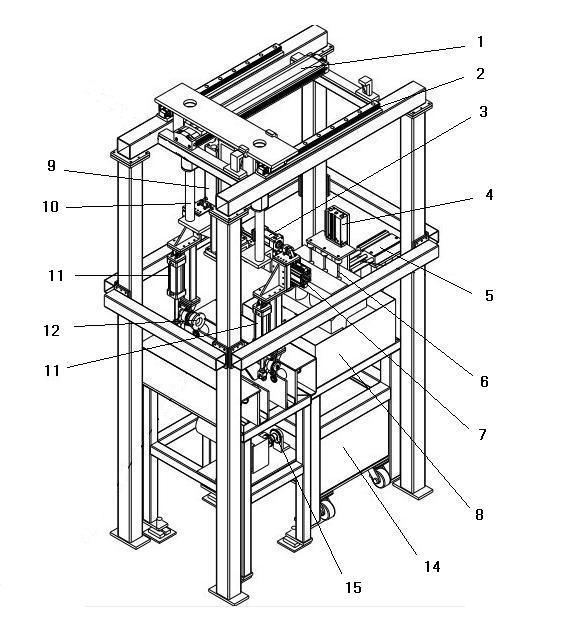
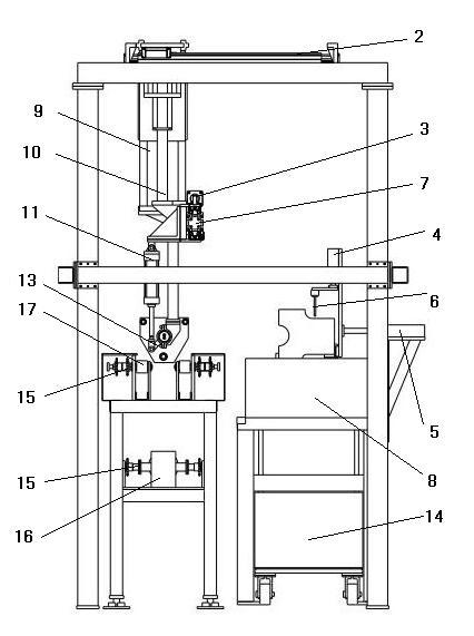
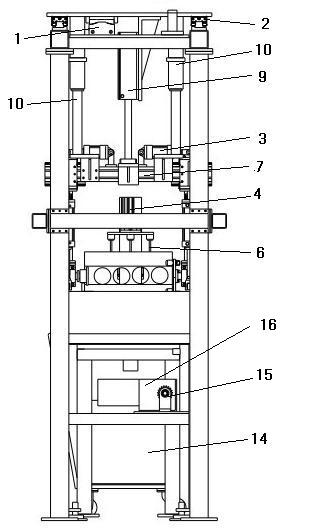
[0014] Example: see figure 1 , figure 2 , image 3 .

[0015] An automatic chip removal device for an engine cylinder, comprising a turning and moving positioning mechanism, a vibration mechanism 8, a high-pressure air blowing mechanism, a product delivery mechanism, an automatic control system, and a debris collection vehicle 14, the turning and moving positioning mechanism includes a horizontal movement mechanism, Up and down moving mechanism, clamping mechanism and rotating mechanism; described high-pressure air blowing mechanism comprises gas nozzle 6, gas nozzle direction adjustment structure; described horizontal moving mechanism, up and down moving mechanism, clamping mechanism, rotating mechanism, vibrating mechanism 8, gas The mouth direction adjustment structure and the movement of the product conveying mechanism are all controlled by the automatic control system.

[0016] The horizontal movement mechanism includes a pneumatic slide table 1 and a guide rail mecha...


PUM


Abstract

The invention relates to the processing field of engine cylinder bodies, and particularly relates to an automatic remnants removing device of an engine cylinder body; the automatic remnants removing device comprises an overturning / moving / locating mechanism, a vibrating mechanism, a high-pressure blowing mechanism, a product transport mechanism, an automatic control system and a remnants collecting trolley, wherein the overturning / moving / locating mechanism comprises a horizontal moving mechanism, an up-down moving mechanism, a clamping mechanism and a rotating mechanism; the high-pressure blowing mechanism comprises an air nozzle and an air nozzle direction adjusting structure; and movements of the horizontal moving mechanism, the up-down moving mechanism, the clamping mechanism, the rotating mechanism, the vibrating mechanism, the air nozzle direction adjusting structure and the product transport mechanism are controlled by the automatic control system. According to the invention, joint action of three methods of vibrating, high-pressure blowing and overturning is used; remnants are removed more cleanly; manual operation is reduced; and production efficiency is increased.

Description

technical field [0001] The invention relates to the field of engine block processing, in particular to an automatic chip removal device for an engine block. Background technique [0002] Since the traditional engine block chip removal equipment adopts the principle of flip type chip removal, it cannot completely remove the iron filings and molding sand remaining in the cylinder block during processing. In order to solve the problem of residual iron filings and molding sand in the cylinder block, it was originally blown manually by wind, so that the production efficiency and labor intensity are very high. So it is necessary to develop a set of dandruff removal device instead of labor. Contents of the invention [0003] The object of the present invention is to solve the above problems, and to provide an automatic chip removal device for an engine block. [0004] In order to realize the purpose of the present invention, the technical scheme adopted in the present inventio...

Claims


Application Information

Patent Timeline
Patent Type & Authority Applications(China)
IPC IPC(8): B08B7/04B08B7/02B08B5/02
Inventor 李钊黄剑徐勇亮
Owner JIANGLING MOTORS
Learn More