

Touch arc striking electric welding machine and electric welding touch arc striking control method
A technology for electric welding machines and electrodes, applied in welding equipment, arc welding equipment, manufacturing tools, etc., can solve problems such as overshoot current not eliminated, achieve the effect of eliminating overshoot current, eliminating welding rod sticking phenomenon, and easy arc starting
- Summary
- Abstract
- Description
- Claims
- Application Information
AI Technical Summary
Problems solved by technology
Method used
Image

Examples
Embodiment approach 1
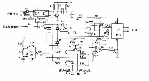
[0041] Embodiment 1 of the present invention: (High frequency inverter voltage type PWM control-1)
[0042] circuit such as figure 2 As shown, the analysis is as follows:
[0043] Phase 1: (no load)
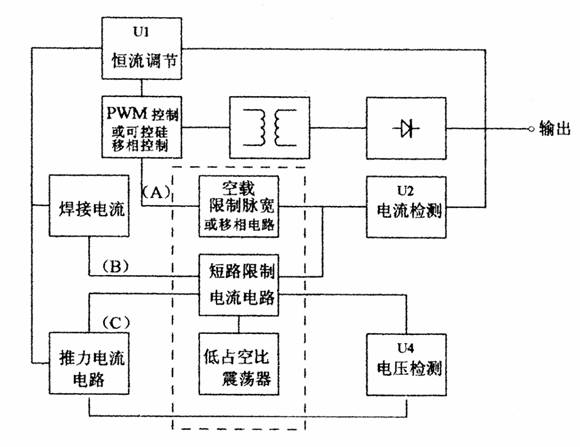
[0044]There is no welding current at no load, current = 0, the given welding current and thrust current are sent to the regulator U1 in negative values, and U1 outputs the maximum value at this time, U3 (3525) is a voltage-type pulse width modulation integrated circuit, the first The voltage of pin 2 determines the output pulse width, and drives the power switching device to achieve adjustable output power. Pin 2 is the maximum output value of U1 at this time!
[0045] No signal from the current sampling circuit is sent to U2 to form a current threshold comparison circuit, U2 outputs low level, U9 4053 electronic switch does not act, the potential of U3 3525 pin 9 (point A) will be pulled down, adjust R13, U3 pin 9 The voltage is clamped at the minimum voltage value of the ...
Embodiment approach 2
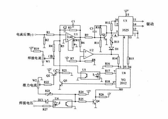
[0053] Embodiment 2 of the present invention: (High frequency inverter voltage type PWM control-2)
[0054] circuit such as image 3 As shown, it is another voltage type PWM control circuit type
[0055] The analysis is as follows: Phase 1: (no load)
[0056] There is no welding current when there is no load, and the given welding current and thrust current are positive values sent to the regulator U1, U1 outputs the minimum value at this time, Q1 is cut off, U3 (3525) is a voltage-type pulse width modulation integrated circuit, the 9th The pin voltage determines the output pulse width, and drives the power switching device to achieve adjustable output power. The 9th foot is the maximum value of the output at this time!
[0057] No signal from the current sampling circuit is sent to U2 to form a current threshold comparison circuit, U2 outputs a low level, R13 will pull down the potential of the 9th pin of U3 (3525) (that is, point A) through D1, and adjust the voltage ...
Embodiment approach 3
[0066] Embodiment 3 of the present invention: (High frequency inverter current type PWM control)
[0067] circuit such as Figure 4 shown, is a current mode PWM control circuit type
[0068] U4 (3846) is a current-mode pulse width modulation integrated circuit, the voltage level of pin 5 determines the output size
[0069] analyse as below:
[0070] Phase 1: (no load)
[0071] There is no welding current when there is no load, and the given welding current and thrust current are sent to the regulator U1 in negative values. At this time, U1 outputs the maximum value, and it is sent to U4 (3846) current-type pulse width modulation integrated circuit 5 through the U2 follower. pin, the voltage level of pin 5 determines the output pulse width, and drives the power switching device to achieve adjustable output power.
[0072] No signal from the current sampling circuit is sent to U2 to form a current threshold comparison circuit, U2 outputs a low level, R13 will pull down the...
PUM
 Abstract
Description
Claims
Application Information