Joint method of aluminum pipe fitting and steel shaft end fitting

A joining method and shaft end technology, which can be used in welding equipment, manufacturing tools, non-electric welding equipment, etc., can solve the problems of weak joint strength, easy splitting, and cannot meet the normal use requirements of the roll core, and achieve a firm joint and increase joint strength. Effect

Active Publication Date: 2012-09-19
斋藤胜雄
View PDF3 Cites 3 Cited by
  • Summary
  • Abstract
  • Description
  • Claims
  • Application Information

AI Technical Summary

Problems solved by technology

However, since the melting point of aluminum is much lower than that of steel, the end face of the aluminum pipe fitting and the end face of the steel shaft end piece cannot be in a molten state at the same time during the friction welding process, resulting in the jointed roll core being only in the aluminum The end surface of the pipe fitting and the end surface of the steel shaft end piece form a shallow joint in the form of a plane. The joint strength of the joint of the roll core is weak, easy to split, and the bending resistance is poor, which cannot meet the normal use requirements of the roll core.

Method used


Image

  • Joint method of aluminum pipe fitting and steel shaft end fitting
  • Joint method of aluminum pipe fitting and steel shaft end fitting
  • Joint method of aluminum pipe fitting and steel shaft end fitting

Examples


Embodiment 1

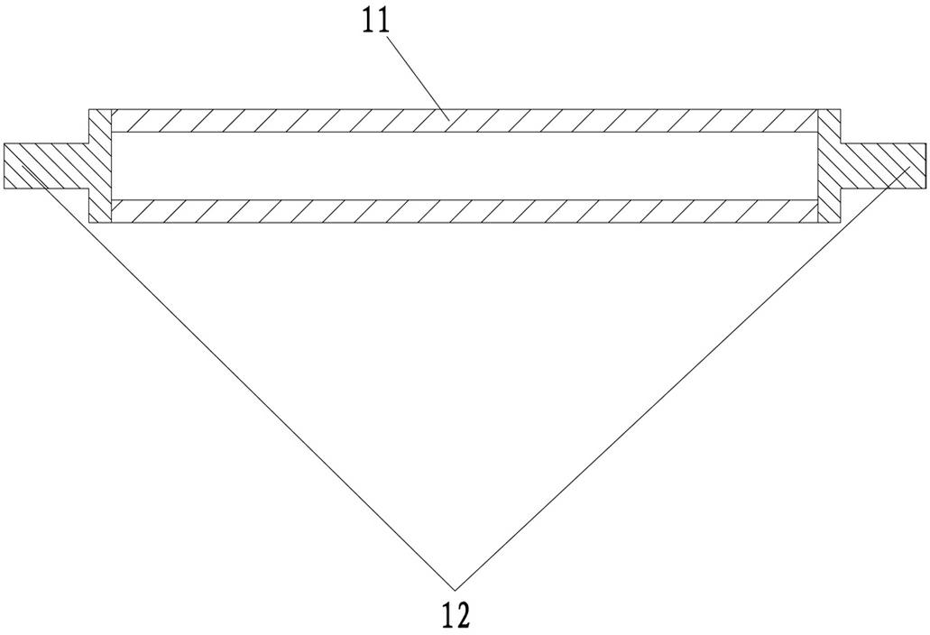
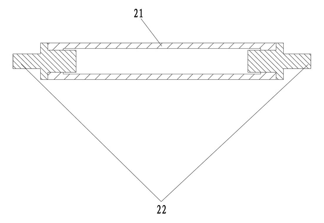
[0020] The joining method of the aluminum pipe fitting 21 whose grade is A6063 and the steel shaft end piece 22 whose grade is SUS416 includes the following steps:

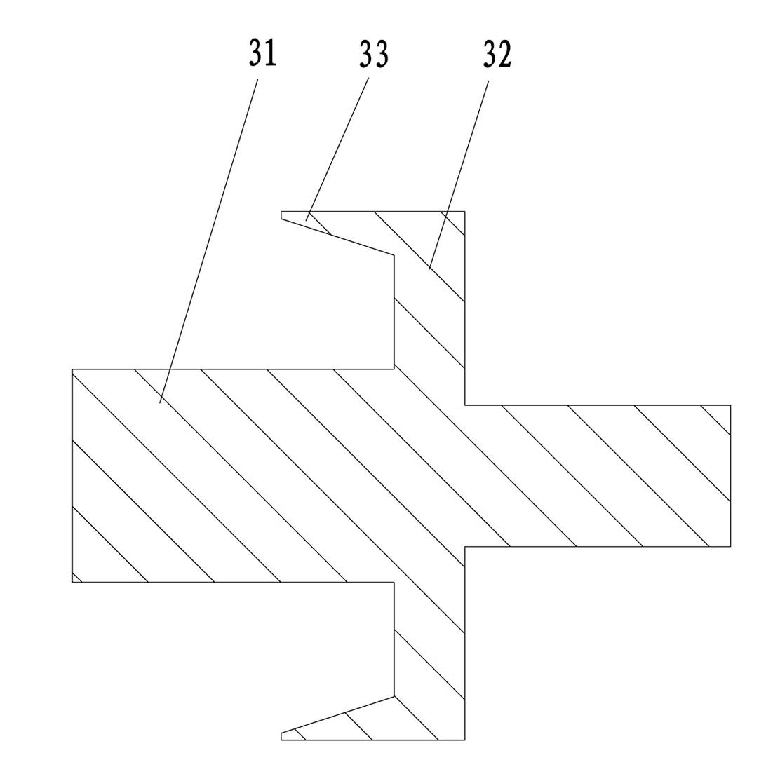
[0021] 1. Forming steel shaft end parts through conventional turning, see image 3 , the steel shaft end piece is divided into three cylinders by steps in the axial direction, the outer diameter of the first cylinder 31 is 8.3 mm, which is slightly smaller than the inner diameter of the hollow aluminum pipe fitting 21 by 10 mm, and the second cylinder 32 is The outer diameter is 16 millimeters, which is slightly larger than the outer diameter of the hollow aluminum pipe fitting 21, which is 13.1 millimeters; the end surface of the second cylinder 32 connected to the first cylinder 31 protrudes from the circumference of the end face and is provided with a thin wall 33 with a variable diameter. The inner diameter of the thin wall 33 gradually increases toward the direction of the first cylinder 31, and the cone angl...

Embodiment 2

[0025] The joining method of the aluminum pipe fitting 41 whose grade is A6063 and the steel axle end piece 42 whose grade is SUS416 comprises the following steps:

[0026] 1. Forming steel shaft end parts through conventional turning, see Figure 5 , the steel shaft end piece is divided into three cylinders by steps along the axial direction, the outer diameter of the first cylinder 51 is 8.3 mm, which is slightly smaller than the inner diameter of the hollow aluminum pipe fitting 41 by 10 mm, and the second cylinder 52 is The outer diameter is 16 millimeters, which is slightly larger than the outer diameter of the hollow aluminum pipe fitting 41, which is 13.1 millimeters; the end surface of the second cylinder 52 connected to the first cylinder 51 protrudes from the circumference of the end face and is provided with a thin wall 53 with a variable diameter. The inner diameter of the thin wall 53 gradually increases toward the direction of the first cylinder 51, and the cone ...


PUM

PropertyMeasurementUnit
Outer diameteraaaaaaaaaa

Abstract

The invention discloses a joint method of an aluminum pipe fitting and a steel shaft end fitting, wherein the method comprises the following steps: a steel shaft end fitting is processed and molded, wherein the steel shaft end fitting is axially divided into at least two sections of cylinders by a step, the outer diameter of the first section of the cylinder is slightly less than the inner diameter of a hollow aluminum pipe fitting, and the outer diameter of the second section of the cylinder is slightly greater than the outer diameter of the hollow aluminum pipe fitting; the end surface peripheral part of the connection of the second section of the cylinder and the first section of the cylinder is provided with a reducing thin wall in a protruding mode, and the inner diameter of the reducing thin wall increases gradually towards the direction of the first section of the cylinder. A joint fitting of the aluminum pipe fitting and the steel shaft end fitting, which is molded by adopting the method provided by the invention, not only forms plane shallow joint on the end surface of the aluminum pipe fitting and the end surface of the steel shaft end fitting, but also tight match also exists in the joint part of the aluminum pipe fitting and the steel shaft end fitting, thus the joint intensity is creased, and the joint fitting has a firm joint effect.

Description

technical field [0001] The invention relates to a production method of a metal joining piece, in particular to a joining method of an aluminum pipe piece and a steel shaft end piece. Background technique [0002] see figure 1 , a roll core structure. In order to reduce the weight of the roll core, the middle part is made of hollow steel pipe fittings. In order to ensure the wear resistance and rigidity of the end of the roll mandrel shaft, the two ends of the roll core are made of steel shaft end pieces. The hollow steel pipe The pipe fittings and the steel shaft end pieces are formed into joints that are fixed in one body by friction welding. [0003] In order to further reduce the weight of the roller core, a hollow aluminum pipe is used in the middle, and then it is fixed with two steel shaft ends by friction welding. However, since the melting point of aluminum is much lower than that of steel, the end face of the aluminum pipe fitting and the end face of the steel sha...

Claims


Application Information

Patent Timeline
IPC IPC(8): B23K20/12B23K20/24
Inventor 斋藤胜雄
Owner 斋藤胜雄
Why Eureka
Try Eureka