Method for manufacturing inner core used for moulding of carbon fiber composite multi-way tube

A manufacturing method and a technology for a multi-pass tube, which are applied in the manufacture of bicycle parts, can solve problems such as cracking, and achieve the effects of ensuring normal molding, improving economic benefits, and preventing excessive expansion and cracking.

Active Publication Date: 2012-09-19
厦门侨兴工业有限公司
View PDF4 Cites 2 Cited by
  • Summary
  • Abstract
  • Description
  • Claims
  • Application Information

AI Technical Summary

Problems solved by technology

During the expansion process of the two air ducts 61, 62, due to competition, the second air duct 62 may expand first and squeeze the first air duct 61, resulting in the overexpanded second air duct 62 not yet filling the inner space. The core 40' cracked on its own, not allowing the carbon fiber composite seatstays 4 to form properly

Method used


Image

  • Method for manufacturing inner core used for moulding of carbon fiber composite multi-way tube
  • Method for manufacturing inner core used for moulding of carbon fiber composite multi-way tube
  • Method for manufacturing inner core used for moulding of carbon fiber composite multi-way tube

Examples


Embodiment 1

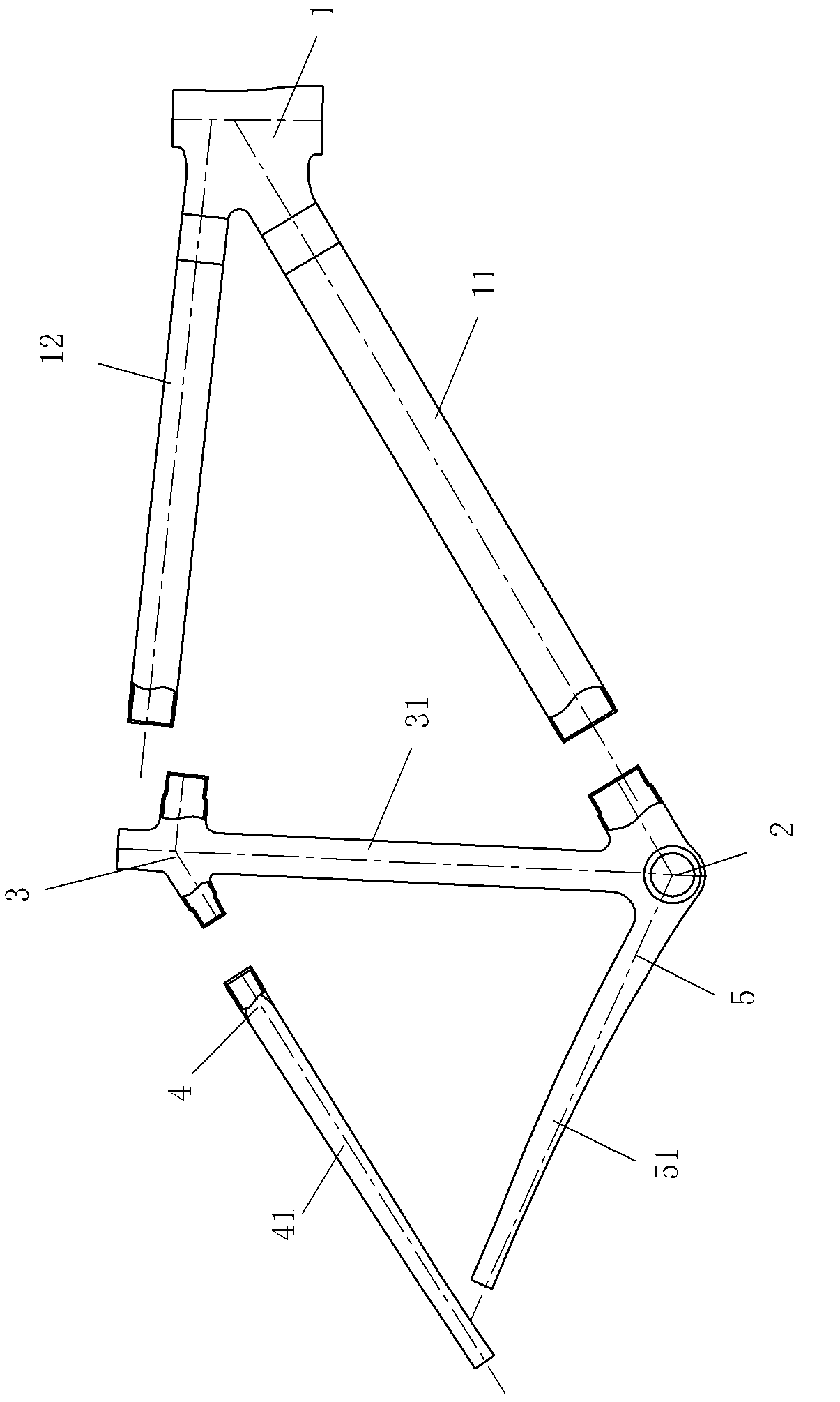
[0031] Adopt the present invention to make and figure 2 The inner core 10 formed by the head pipe corresponding to the carbon fiber composite material head pipe 1 . The inner core 10 that adopts the present invention to manufacture car head tube molding has the following steps:

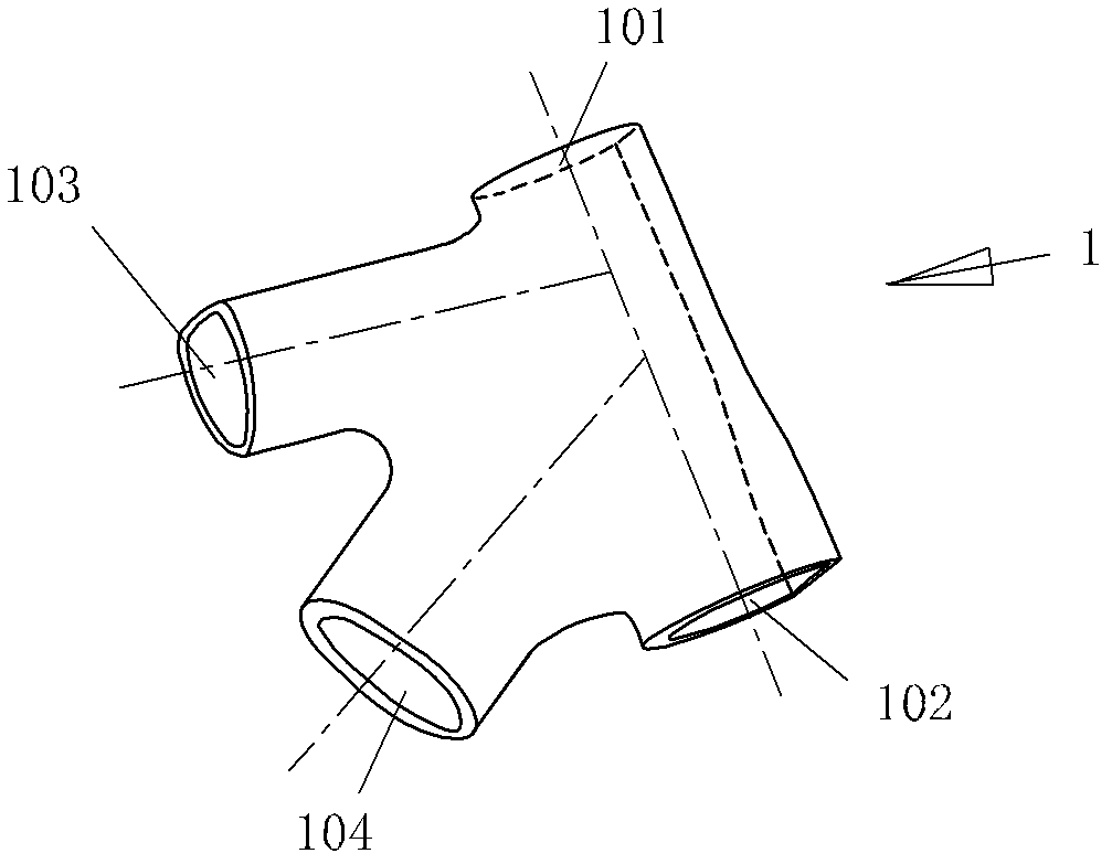
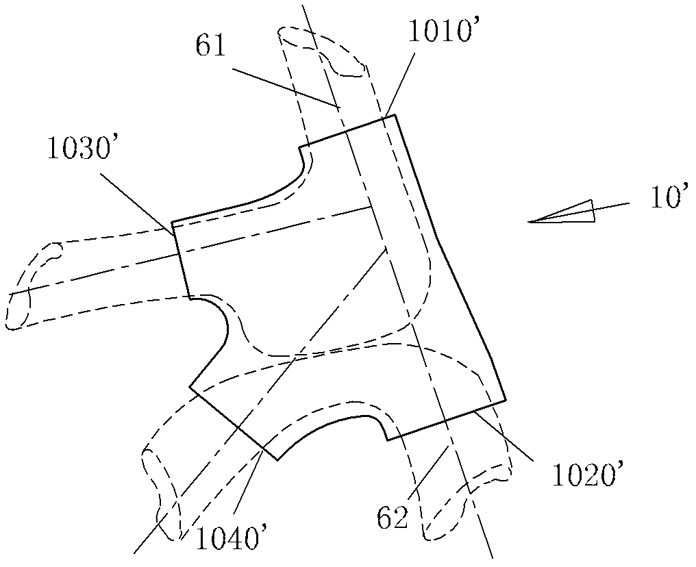
[0032] Step 1, according to the shape of the inner wall of the head pipe 1, split it horizontally along the middle part, and design a thin-walled first core pipe part 110 and a thin-walled second core pipe part 120. The first core tube 110 only has an upper port 1010 corresponding to the upper port 101 of the head pipe 1 and a rear upper port 1030 corresponding to the rear upper port 103 of the head pipe 1 , and is only for inserting one air duct 61 . The second core pipe 120 only has a lower port 1020 corresponding to the lower port 102 of the headpipe 1 and a rear lower port 1040 corresponding to the rear lower port 104 of the headpipe 1 and is only used for inserting another air duct 62 . The su...

Embodiment 2

[0037] Present embodiment adopts the present invention to make and figure 2 The inner core 100 formed by the carbon fiber composite head pipe 1 corresponding to the head pipe has the following steps:

[0038] Step 1, according to the shape of the inner wall of the head pipe 1, split it horizontally along the middle part, and design a thin-walled first core pipe part 1100 and a thin-walled second core pipe part 1200. The first core pipe 1100 only has an upper port 10100 corresponding to the upper port 101 of the head pipe 1 and a rear upper port 10300 corresponding to the rear upper port 103 of the head pipe 1 , and is only for inserting one air duct 61 . The second core pipe 1200 only has a lower port 10200 corresponding to the lower port 102 of the headpipe 1 and a rear lower port 10400 corresponding to the rear lower port 104 of the headpipe 1 and is only used for inserting another air duct 62 . The surface adjacent to the second core pipe part 1200 on the first core pipe ...

Embodiment 3

[0043] Present embodiment adopts the present invention to make and figure 2 The inner core 1000 formed by the carbon fiber composite head pipe 1 corresponding to the head pipe has the following steps:

[0044] Step 1, according to the shape of the inner wall of the head pipe 1, it is split longitudinally, and designed into a thin-walled straight core pipe 11000 and a thin-walled U-shaped core pipe 12000. The straight core pipe 11000 only has an upper port 101000 corresponding to the upper port 101 of the headpipe 1 and a lower port 102000 corresponding to the lower port 102 of the headpipe 1 , and is only used for inserting one air duct 61 . The U-shaped core pipe piece 12000 has only the rear upper port 103000 corresponding to the upper port 101 of the head pipe 1 and the rear lower port 104000 corresponding to the rear lower port 104 of the head pipe 1 and is only for inserting another air duct 62 . The surface adjacent to the U-shaped core pipe 12000 on the straight core...


PUM


Abstract

The invention provides a method for manufacturing an inner core used for moulding of a carbon fiber composite multi-way tube, relating to a method for making a bicycle part. The method comprises the following steps of: step one, designing at least two thin-wall core pipe fittings according to shape of the inner wall of the multi-way tube, wherein each core pipe fitting is only provided with two ports and only one air pipe can be inserted; adjacent surfaces of two adjacent core pipe fittings form a butt joint surface and can be spliced into a complete inner core used for the multi-way tube moulding according to the butt joint surface, the outer surface of the inner core is the same with the shape of the inner surface of the multi-way tube, and dimension of the outer surface of the inner core is slightly smaller than the dimension of the inner surface of the multi-way tube; and any port of the multi-way tube correspond to a corresponding port of one core pipe fitting or correspond to a butt joint combination of corresponding ports of adjacent core pipe fittings; step two, respectively manufacturing the core pipe fittings; and step three, splicing the core pipe fittings into a whole according to the butt joint surface, thus the inner core is formed. The manufactured inner core can put an end to overexpansion and fracture of the air pipe, and the moulding of the carbon fiber composite multi-way tube can be guaranteed to be normal.

Description

technical field [0001] The invention relates to a manufacturing method of a bicycle component. Background technique [0002] To make a carbon fiber composite bicycle frame, the overall frame is generally split into several pipe fittings. The composition of carbon fiber composite bicycle frame, such as figure 1 Shown: there are mainly five multi-way pipes, the first is the head pipe 1 (four-way pipe) connecting the front fork, the front end of the down pipe 11 and the front end of the upper pipe 12; and the bottom bracket tube 2 at the lower end of the standpipe 31; the third is the seat tube 3 (four-way tube) connecting the seat cushion, the rear end of the upper tube 12, the upper end of the stand tube 31 and the front end of the seat stay 4; the fourth is to connect the seat tube 3 rear end and the seat stay 4 (tee pipe) of two upper fork pipes 41; It is difficult for each multi-way pipe to be preformed directly with carbon fiber wrapping, so the industry uses materials...

Claims


Application Information

Patent Timeline
Patent Type & Authority Applications(China)
IPC IPC(8): B29C70/54
Inventor 许清流
Owner 厦门侨兴工业有限公司
Why Eureka
Try Eureka