Methods for electrospin coating and laminating of endoluminal prostheses

a technology of endoluminal prosthesis and electrospin coating, applied in the field of medical devices and methods, can solve the problems of dissolving the inner layer and creating an undifferentiated polymer mass, and achieve the effects of preventing rupture, promoting tissue-ingrowth, and inhibiting further dilation

Active Publication Date: 2020-12-29
XELTIS AG
View PDF11 Cites 1 Cited by
  • Summary
  • Abstract
  • Description
  • Claims
  • Application Information

AI Technical Summary

Benefits of technology

[0008]The present invention provides methods, materials, apparatus, and systems for the fabrication of covered stents, also referred to as grafts, used for a variety of intravascular and other intraluminal purposes. A particular use will be in Thoracic Endovascular Aortic Repair (TEVAR) procedures where the covered stents line the interior of an aortic aneurysm to inhibit further dilation and prevent rupture. The covered stents of the present invention will have a porous cover layer which promotes tissue-ingrowth and “merging” of the material with the native wall. In vivo implantation of the covered stents may be performed using a minimally invasive approach by crimping the device and delivering the devise intravascularly and / or transcutaneously to the site of implantation. The covered stents will have a particularly high recovery which will help prevent endovascular leaks after implantation. Another particular use will be as the base or anchor component of a prosthetic heart or other valve where high recovery will help assure proper seating of the valve in the native annulus while minimizing leakage around the valve.
[0009]The present invention can also provide a docking station or tubular body that acts as an adapter rather than just a support structure and will be configurable to provide more complex shapes in addition to straight tubes as in U.S. Pat. No. 7,922,761, described above. The tubular supports of the present invention will be particularly useful to provide or be docked with prosthetic valves where the tubular support serves as an outer support which is attached to or integrated with valve leaflets which may be formed at last partly from the same materials as the docking station or scaffold. Preferred materials for the tubular support include electrospun, porous polymers that can be formed into scaffolds to provide the support and can also be molded or otherwise formed to provide the valve leaflets. The electrospun or other porous encapsulating materials are preferably resorbable, absorbable, or degradable materials which allow for cell and tissue integration to aid prevention, reduction or elimination of endoleakage.
[0012]Still other approaches include using a focusing ring to accelerate jet and hinder whipping where the focusing ring is positively charged which elongates the straight region of the jet. The focusing ring can be switched off after wet spinning. The solution flow rate can be altered to selectively force a whipping or straight jet formation. Larger nozzle diameters might be employed to achieve a linear jet. By suturing the environment with solvent, drying of the fibers would be inhibited, and use of gas sheath would reduce whipping due to high solvent amount on fibers surface.
[0020]In other embodiments, an adhesive layer may be formed between the inner and outer layers by delivering a second solution over the endoluminal prosthesis between steps (d) and (e) while applying an electrical potential to produce a second set of fibers (the adhesive layer described above) between the inner and outer layers formed by the first and the third sets of fibers, respectively. The electrical potential between the target and the applicator is adjusted to produce a higher solvent fraction in the second set of fibers that allows the second set of fibers to act as an adhesive between the first and the third sets of fibers.

Problems solved by technology

The flowability should however not be increased so much that the material reaches the target with a wetness that would result in residual solvent and material soaking through the inner layer, potentially dissolving inner layer as well as creating an undifferentiated polymer mass.

Method used


Image

  • Methods for electrospin coating and laminating of endoluminal prostheses
  • Methods for electrospin coating and laminating of endoluminal prostheses
  • Methods for electrospin coating and laminating of endoluminal prostheses

Examples


examples

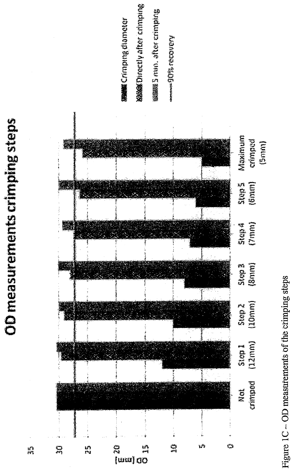
[0032]Materials and Methods. Pictures were taken from the stent, before, during and after the experiment. Visual inspection was performed at all steps and written down in the study plan. In the study plan it was determined to crimp the stent to 12 mm, 10 mm, 8 mm, 6 mm, 5 mm and maximum possible for 5 minutes at each step. Because it was observed that it was most likely not possible to crimp the stent beyond 5 mm, an extra step of 7 mm was added. The outer diameter (OD) of the stent was measured and written down in the study plan, before crimping, directly after and 5 minutes after each crimping step. After crimping the stent to the maximum step of 5 mm, the stent was put into PBS. Pictures were made and the OD was measured at t=0, 5, 10, 15, 20 and 60 minutes. The ID of the sample that was tested was 30.30.080 T2.

[0033]The stents were prepared as follows. A first electrospinning solution was spun over a 29 mm cylindrical target, rotating at 100 RPM, to form the inner layer of the c...


PUM

PropertyMeasurementUnit
electromotive forcesaaaaaaaaaa

Abstract

Endoluminal and other as implantable prostheses are fabricated in electrospinning apparatus including a target and an applicator. A solution comprising a polymer and a solvent is directed to the target with a first electrical potential between the target and the applicator to produce a first set of fibers. The same or another solution is continued to be delivered through the applicator onto the target while applying a second electrical potential to produce a second set of fibers having a second solvent fraction, and the same or different solution may be delivered while applying a third potential difference to produce a laminated structure having at least three layers. By properly controlling the electrical potentials and solvent fractions, an adhesive layer can be formed to serve a glue or adhesive between the inner and outer layers, and a stent or other scaffold may be positioned between the inner and outer layers to form a covered stent or graft.

Description

CROSS-REFERENCE TO RELATED APPLICATIONS[0001]This application is a 371 of PCT / IB2016 / 001529 filed on Oct. 3, 2016. PCT / IB2016 / 001529 claims the benefit of U.S. Provisional Application 62 / 236,073 filed on Oct. 1, 2015, the entire content of which is incorporated herein by reference.BACKGROUND OF THE INVENTION1. Field of the Invention[0002]The present application relates generally to medical devices and methods. More particularly, the present invent relates to methods for coating and laminating implants such as endoluminal prostheses.[0003]A medical stent is a type of endoluminal prosthesis which is implanted in a body lumen to open or create a passage therethrough. Most commonly, stents act as “scaffolds” to hold open a diseased or blocked region in a natural body lumen such as in the vasculature, biliary tract, and urinary tract. Stents are often coated or laminated in order to increase biocompatibility and / or create a barrier so that the stent can act as a graft. Such laminated ste...

Claims


Application Information

Patent Timeline
Patent Type & Authority Patents(United States)
IPC IPC(8): D01D5/00D04H1/728A61L27/34A61L31/10A61L27/18
CPCD01D5/0092A61L31/10D01D5/0046A61L27/34A61L27/18D01D5/0084D01D5/0061D01D5/0069D04H1/728A61L2420/02D10B2509/06
Inventor EDOUARD NAZ, CHRISTOPHE PIERRENANDAKUMAR, ANANDKUMARSVANIDZE, OLEGCOX, MARTIJN ANTONIUS JOHANNESVOLPATO, FABIO ZOMER
Owner XELTIS AG
Why Eureka
Try Eureka