Sliding roof system

A sunroof and sliding guide technology, which is applied to engine components, engine seals, roofs, etc., can solve the problems of large structural width of opening and closing mechanisms and guide rails

Active Publication Date: 2012-09-19
DAIMLER AG
View PDF8 Cites 0 Cited by
  • Summary
  • Abstract
  • Description
  • Claims
  • Application Information

AI Technical Summary

Problems solved by technology

This results in a large structural width of the opening mechanism and guide rail

Method used


Image

  • Sliding roof system
  • Sliding roof system
  • Sliding roof system

Examples


Embodiment Construction

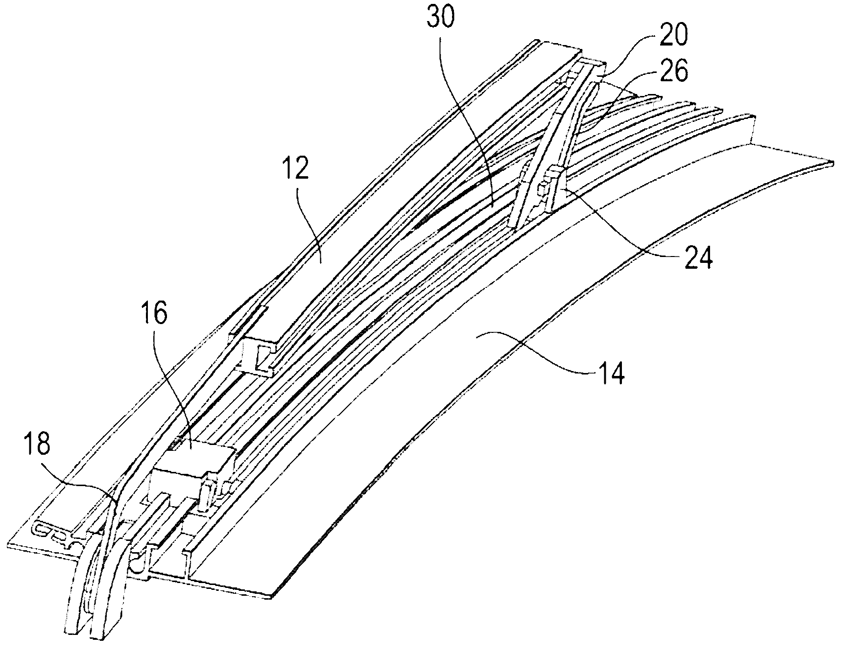
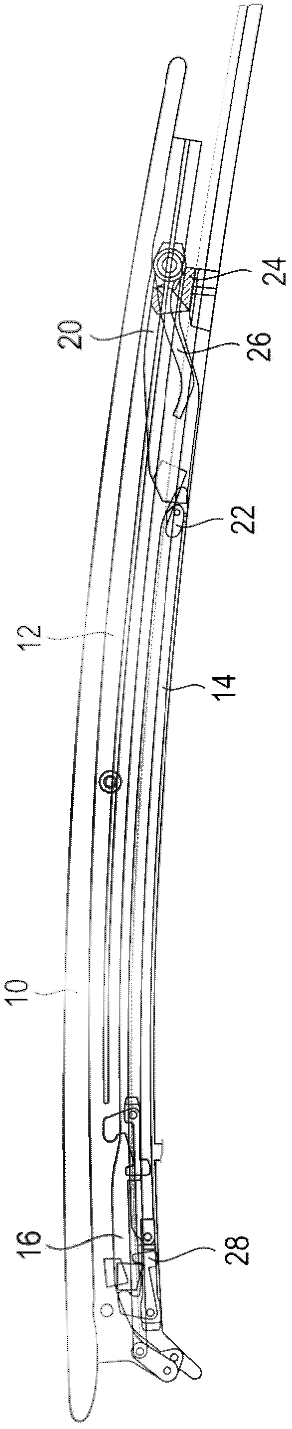
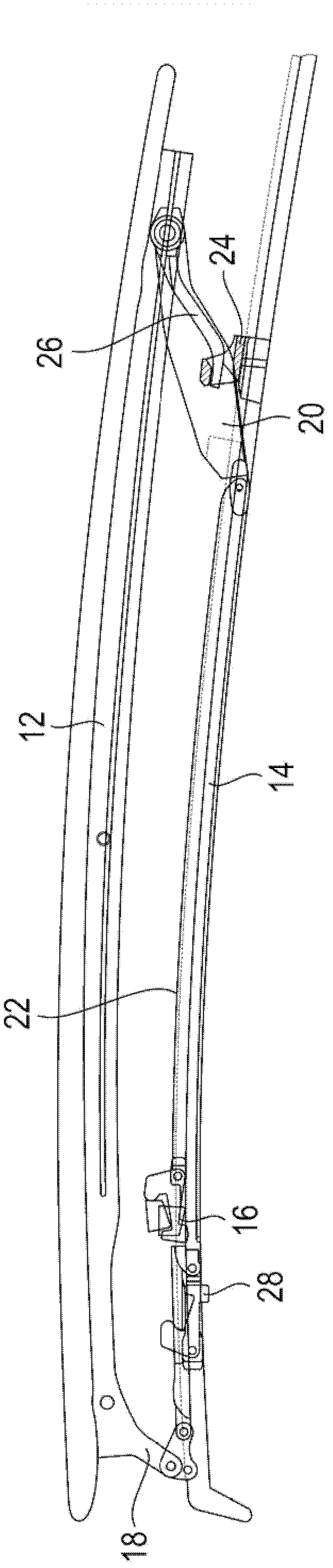
[0027] Follow the attached Figures 5 to 11 , the configuration of the sliding sunroof system according to the invention will be described with regard to the rear opening and closing arm 20 . For the components known from the above description of the background art, the same reference numerals are used and reference is made to the above description.

[0028] The guide rail 14 is very compact in the transverse direction in the sliding sunroof system according to the invention, because the slide block 16 and the opening arm 20 are arranged in the same guide rail 30 (see especially Figure 5 ). The opening and closing arm 20 is arranged on the guide rail 14 via a pivot bearing 32 , the pivot axis of which is arranged approximately perpendicular to the longitudinal direction of the guide rail 14 and is embodied in the support body 24 . The support body is arranged on the guide rail 14 such that the pivot axis of the pivot bearing 32 is located below the plane of the guide rail 1...


PUM


Abstract

A sliding roof system, in particular for motor vehicles, with at least one guide rail (14), a carriage (16) which is shiftable in the guide rail (14), a guide element (18) located at the front, which can cooperate with a cover (10) of the sliding roof, and a swing-out lever (20) located at the rear, which likewise can cooperate with the cover (10) and can be moved by the carriage (16) from a starting position into a position swung out, is wherein the swing-out lever (20) is mounted on the guide rail (14) with a fixed swivel axis (32) and that at least in the starting position the end of the swing-out lever (20) associated to the cover (10) lies on the side of the swivel axis (32) facing the carriage (16).

Description

technical field [0001] The invention relates to a sliding sunroof system, in particular for motor vehicles, having at least one guide rail, a slide block, which can slide in the guide rail, and a front guide element, which is connected to the roof of the sliding sunroof. The lid cooperates with a rear opening arm, which likewise cooperates with the top cover and can be moved from an initial position into an open position by slides. Background technique [0002] A kind of such sliding sunroof system is already known from EP 2 072 304 A, and in the following press Figures 1 to 4 to narrate. The sliding sunroof system is used to incorporate a roof 10 (see figure 2 ) from a closed position, in which the window on the sunroof is closed, through various intermediate positions (for example, a ventilation position) to an open position, in which the window in the sunroof is substantially opened. A cover holder 12 is provided on the cover 10 , which is movably coupled to a guide r...

Claims


Application Information

Patent Timeline
Patent Type & Authority Applications(China)
IPC IPC(8): B60J7/043B60J10/82
CPCB60J7/0435B60J7/024
Inventor R·格林姆J·施洛德A·戴蒙
Owner DAIMLER AG
Why Eureka
Try Eureka