Removing pipe clamp for roller turning lathe

A roll lathe and de-piping technology, which is applied in the direction of expanding mandrels, etc., can solve the problems of increasing labor intensity of workers, time-consuming and laborious work, and increasing workload, etc., and achieves shortening of processing auxiliary time, quick and easy replacement of de-piping, and reduced The effect of labor intensity

Inactive Publication Date: 2019-06-28
天津如纳福科技有限公司
View PDF0 Cites 0 Cited by
  • Summary
  • Abstract
  • Description
  • Claims
  • Application Information

AI Technical Summary

Problems solved by technology

[0002] At present, on the roll lathe, there are many types of processing jigs for detachable parts, the structure is more complicated, and the loading and unloading is inconvenient. Using the jig core to match the taper hole of the main shaft increases the workload and increases the difficulty of assembly, and every tim

Method used


Image

  • Removing pipe clamp for roller turning lathe

Examples


Embodiment 1

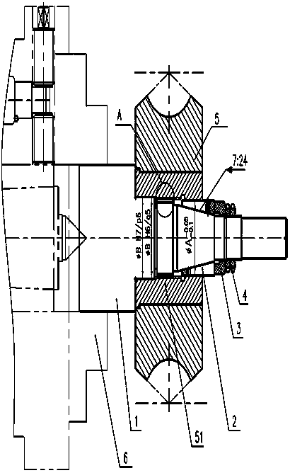
[0011] Embodiment 1: as figure 1 As shown, a tube removal fixture for a roll lathe includes a core body 1, and the tube removal part 5 is sleeved on the core body 1 through a sleeve hole 51 provided thereon, and is fixed by a tensioning device . The sleeve hole 51 on the detachable part 5, one side of the sleeve hole 51 and the core body 1 is a clearance fit or an interference fit, that is, the φB H6 / g5 or φB H7 / P6 mentioned in the figure A section of the core body 1 corresponding to the other side of the sleeve hole 51 is in the shape of a cone, and the tensioning device is arranged in cooperation with the section of the core body in the shape of the cone. The tensioning device includes a tensioning sleeve 2 matched with a section of the conical core, and the tensioning sleeve 2 is compressed by a flange 3 and a fastening nut 4 . The taper fit between the tensioning sleeve 2 and the section of the conical core is 7:24.

[0012] Assembly process of the present invention is:...


PUM


Abstract

The invention relates to a turning lathe clamp for machining removing pipe parts. A removing pipe clamp for a roller turning lathe comprises a core body; and a removing pipe part is arranged on the core body in a sleeving manner through a sleeving hole in the removing pipe part, and is fixed through an expanding device. The removing pipe clamp device is easy to assemble and disassemble, reliable in application, simple in structure, easy to assemble, and capable of making removing pipe replacing fast and easy, greatly shorting the machining auxiliary time, and lowering the labor intensity of aworker.

Description

technical field [0001] The invention relates to a lathe fixture for processing detached tube parts. Background technique [0002] At present, on the roll lathe, there are many types of processing jigs for detachable parts, the structure is more complicated, and the loading and unloading is inconvenient. Using the clamp core to match the spindle taper hole increases the workload and increases the difficulty of assembly, and every time the tube is disassembled, the nut must be loosened, and the screw can be screwed to eject the tube for replacement. When installing and removing the tube, the screw must be screwed first and then Screwing the nut to lock and take off the pipe will prolong the auxiliary time and increase the labor intensity of the workman. Contents of the invention [0003] Aiming at the problems existing in the prior art, the present invention provides a pipe-removing fixture for a roll lathe with simple structure, convenient replacement and processing of pip...

Claims


Application Information

Patent Timeline
IPC IPC(8): B23B31/40
Inventor 不公告发明人
Owner 天津如纳福科技有限公司
Why Eureka
Try Eureka