Automatic balancing hoop bending machine capable of achieving arc wire feeding

An automatic balancing and hoop bending machine technology, applied in the field of hoop bending machines, can solve the problems of high cost, cumbersome operation, complex structure, etc., and achieve the effects of low production cost, reduced labor, and high degree of automation

Active Publication Date: 2016-11-23
陕西勇拓机械科技有限公司
View PDF14 Cites 0 Cited by
  • Summary
  • Abstract
  • Description
  • Claims
  • Application Information

AI Technical Summary

Problems solved by technology

[0007] Aiming at the technical problems of complex structure, cumbersome operation and high cost in the existing hoop bending machine in the background technology, the purpose of the present invention is to propose an automatic balance hoop bending machine for arc-shaped wire feeding, which can Realize automatic balance adjustment

Method used


Image

  • Automatic balancing hoop bending machine capable of achieving arc wire feeding
  • Automatic balancing hoop bending machine capable of achieving arc wire feeding
  • Automatic balancing hoop bending machine capable of achieving arc wire feeding

Examples


Embodiment 1

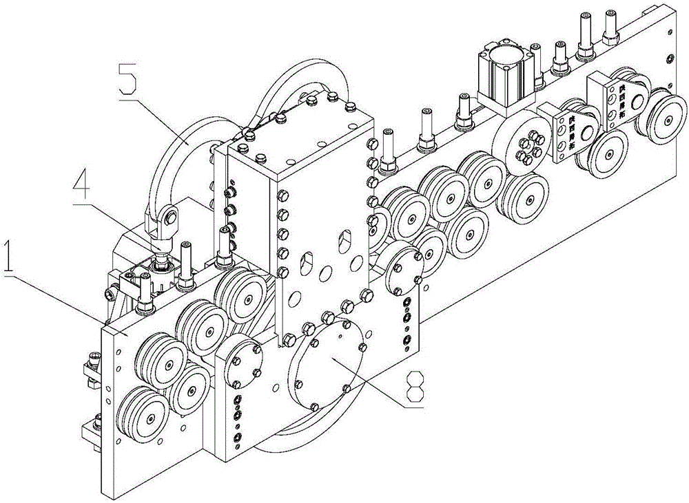
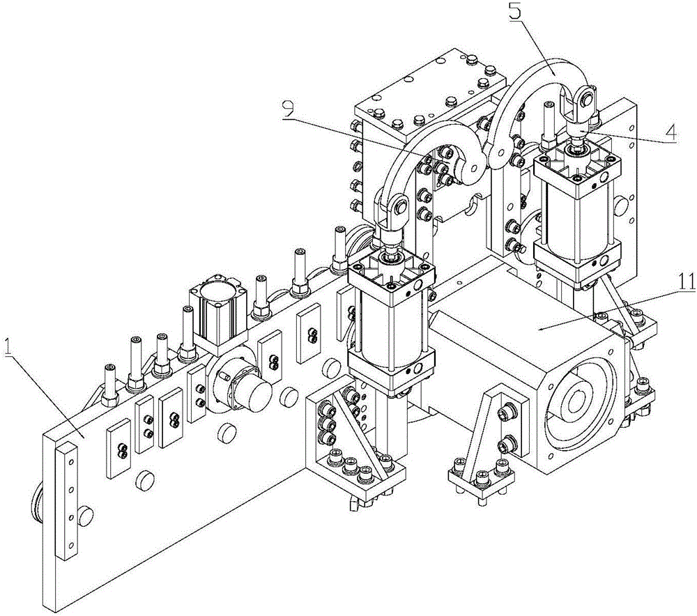
[0041] Such as Figure 1 to Figure 3 As shown, an arc-shaped wire feeding automatic balance hoop bending machine provided by the present invention includes a frame 1 and a traction mechanism arranged on the frame 1. The traction mechanism includes a main driving wheel 8 and is located above the main driving wheel 8. At least one pressure roller group, each pressure roller group is composed of at least two pressure rollers 2 arranged side by side along the feeding direction of the steel bar 12; the outer edge of the main driving wheel 8 is provided with a slot 10, the at least two A pressure wheel 2 is pressed on the steel bar 12 in the socket 10 of the main driving wheel 8; one end of the main driving wheel 8 is connected to a rotating power source 11, and the rotating power source 11 is supported on the frame 1; at least two of the pressing wheels 2 It is arranged on the depressing mechanism for adjusting its position, and the depressing mechanism is arranged on the frame 1; ...

Embodiment 2

[0044] On the basis of Embodiment 1, the number of the eccentric shaft pressing mechanism can be selected according to actual needs. Of course, the present invention is not limited to the cases enumerated in this embodiment.

[0045] If only one steel bar 12 is conveyed, the eccentric shaft type depressing mechanism can be formed into one group. At this time, a caulking groove 10 is arranged on the outer edge of the main driving wheel 8, and the at least two pressing wheels 2 They are arranged side by side along the feeding direction of the reinforcing bars 12 and pressed against the reinforcing bars 12 in the said one embedding groove 10 . When conveying a steel bar 12 of uneven thickness, the pressure roller adjustment plate 3 will rotate a certain angle to the pressure roller that cannot be pressed under the pressure of the eccentric shaft type pressing mechanism, and automatically adjust the balance state so that the two pressure rollers 2 can be compressed, and the reinf...

Embodiment 3

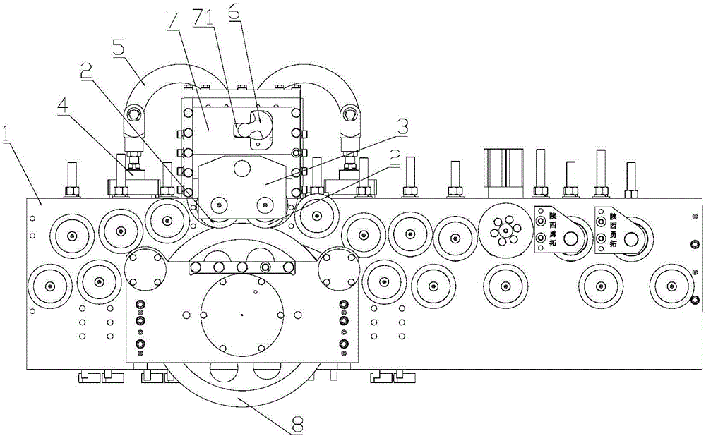
[0048] On the basis of Example 1, such as figure 1 , 3 , 5, and 8, the eccentric shaft type depressing mechanism includes a depressing reciprocating drive mechanism 4 fixed on the frame 1, and the connecting rod 5 of the depressing reciprocating drive mechanism 4 is connected to one end of the eccentric shaft 6, and the eccentric shaft 6 The other end of the slide plate 7 is movably connected; the slide plate 7 is hinged with the pressure roller adjustment plate 3, and the pressure roller adjustment plate 3 is hinged with at least two pressure rollers 2, and at least two pressure rollers 2 are along the feed of the steel bar 12 Directions are set front to back and side by side.

[0049] The depressing reciprocating drive mechanism 4 is an air cylinder, an oil cylinder, a lead screw, a screw rod or an electric pressing device driven by a motor. In this implementation, the preferred cylinder is simple in structure and convenient in maintenance.

[0050] Such as image 3 , ...


PUM


Abstract

The invention relates to hoop bending machines, in particular to an automatic balancing hoop bending machine capable of achieving arc wire feeding. The automatic balancing hoop bending machine comprises a rack and a traction mechanism arranged on the rack, wherein the traction mechanism comprises a main driving wheel and at least one pressing wheel group positioned above the main driving wheel; each pressing wheel group comprises at least two pressing wheels which are arranged side by side in the rebar feeding direction; caulking grooves are formed in the edge of the main driving wheel; the at least two pressing wheels are pressed on rebars in the caulking grooves of the main driving wheel; the at least two pressing wheels are arranged on a downward pressing mechanism used for adjusting the position; the downward pressing mechanism is arranged on the rack; the downward pressing mechanism is an eccentric shaft type downward pressing mechanism; the eccentric shaft type downward pressing mechanism is hinged to a pressing wheel adjusting plate; and the at least two pressing wheels are hinged to the pressing wheel adjusting plate. According to the automatic balancing hoop bending machine, a fine adjustment elastic downward pressing structure is avoided, and no matter a single rebar or two rebars, the rebars can be tightly pressed by the pressing wheels; and besides, the eccentric shaft type downward pressing mechanism is simple in structure, and the friction frequency can be reduced.

Description

technical field [0001] The invention relates to a hoop bending machine, in particular to an automatic balance hoop bending machine for arc-shaped wire feeding. Background technique [0002] The hoop bending machine is generally composed of a feeding mechanism, a straightening mechanism, a traction mechanism, a bending mechanism and a cutting mechanism. The feeding mechanism stops working after feeding the steel bar into the steel bar hoop bending machine. Under the traction of the traction mechanism, the steel bar is first straightened by the straightening mechanism, then bent into a preset shape by the bending mechanism, and finally the steel bar bent into a certain shape passes through After the cutting mechanism is cut, it can be used to assemble the steel skeleton. [0003] Chinese patent application number 201310034480.9 discloses a torsion-resistant steel bar feeding mechanism, which includes a frame and a traction mechanism arranged on the frame. The traction mechani...

Claims


Application Information

Patent Timeline
Patent Type & Authority Applications(China)
IPC IPC(8): B21F1/00B21F23/00
CPCB21F1/004B21F23/002
Inventor 姜勇
Owner 陕西勇拓机械科技有限公司
Why Eureka
Try Eureka