
Hybrid power and heat generating device

a hybrid power and heat generating technology, applied in the safety of solar heat collectors, thermal-pv hybrid energy generation, lighting and heating apparatus, etc., can solve the problems of serious damage to the cooling circuit, unwanted increase of cooling media, etc., and achieve the effect of improving the heat transfer efficiency of the cooling pla

Pending Publication Date: 2022-02-03
SAMSTER AB
View PDF5 Cites 0 Cited by
  • Summary
  • Abstract
  • Description
  • Claims
  • Application Information

AI Technical Summary

Benefits of technology

The present invention is a hybrid power and heat generating device that includes a photovoltaic solar power collector and a heat exchanging unit. The heat exchanging unit cools the solar collector by using a cooling plate that is in contact with a cooling medium. The device can operate in two modes: a normal mode where the gap between the cooling plate and the solar collector is filled with water vapor, and a security mode where the gap is filled with air to reduce heat transfer. The cooling plate can be attached to the solar collector using an expandable elongated profile that applies pressure on the cooling plate. The technical effect of this invention is to improve the efficiency and reliability of solar power generation and utilization.

Problems solved by technology

Such unwanted increase of the cooling media may occur e.g. if there is a power failure or other failure which prevents or interrupts the circulation of cooling media through the heat exchanging unit.
If the cooling media circulation is stopped and additional heat is transferred from the photovoltaic collector to the cooling medium, there is a risk that the cooling media may reach its boiling temperature which may seriously damage the cooling circuit, especially the piping conducting the cooling medium.

Method used


Image

  • Hybrid power and heat generating device
  • Hybrid power and heat generating device
  • Hybrid power and heat generating device

Examples


Embodiment Construction

[0053]In the present detailed description, various embodiments of a power generation device and system according to the present disclosure are described. However, this invention may be embodied in many different forms and should not be construed as limited to the embodiments set forth herein; rather, these embodiments are provided for thoroughness and completeness, and fully convey the scope of the invention to the skilled person. Like reference characters refer to like elements throughout.

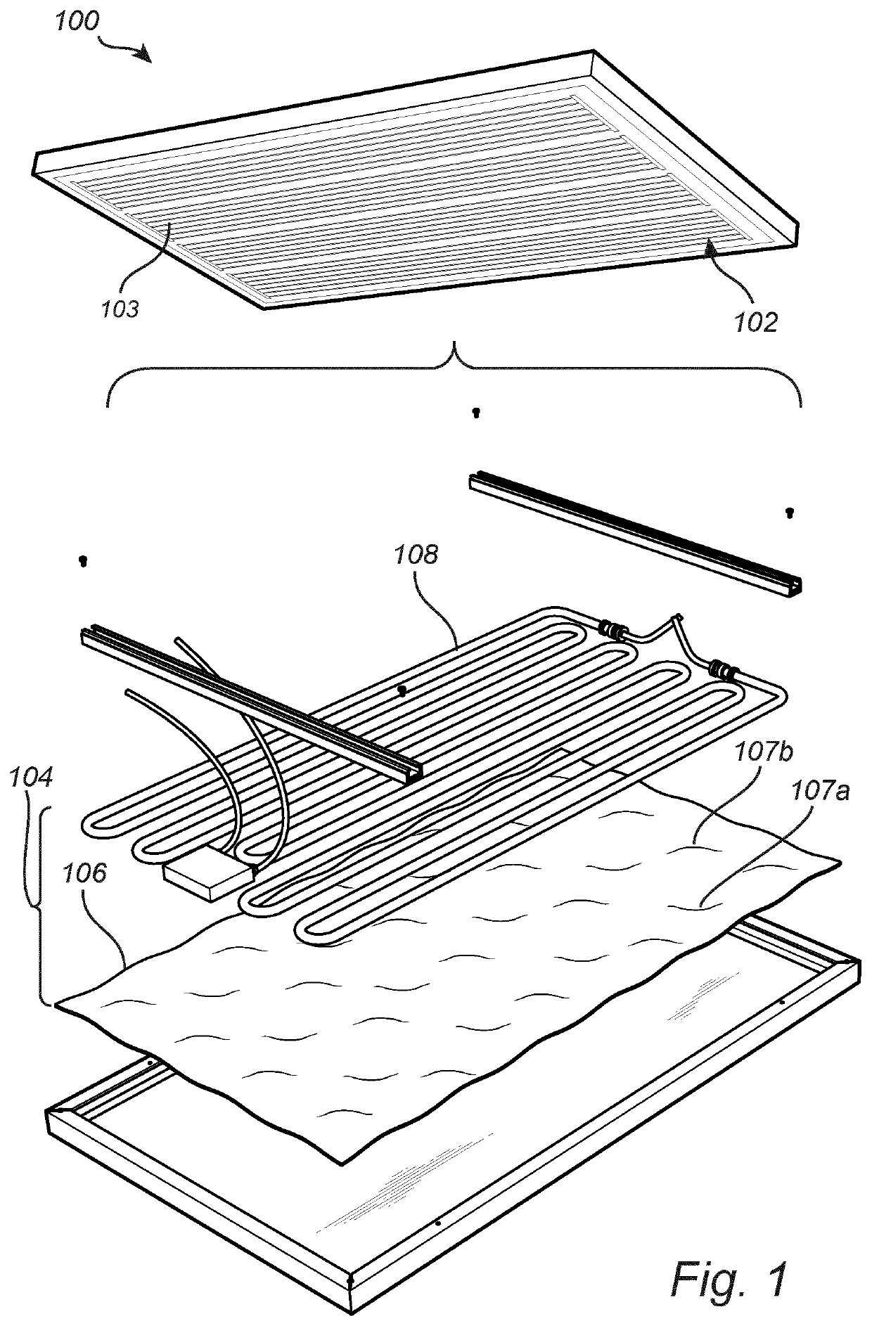
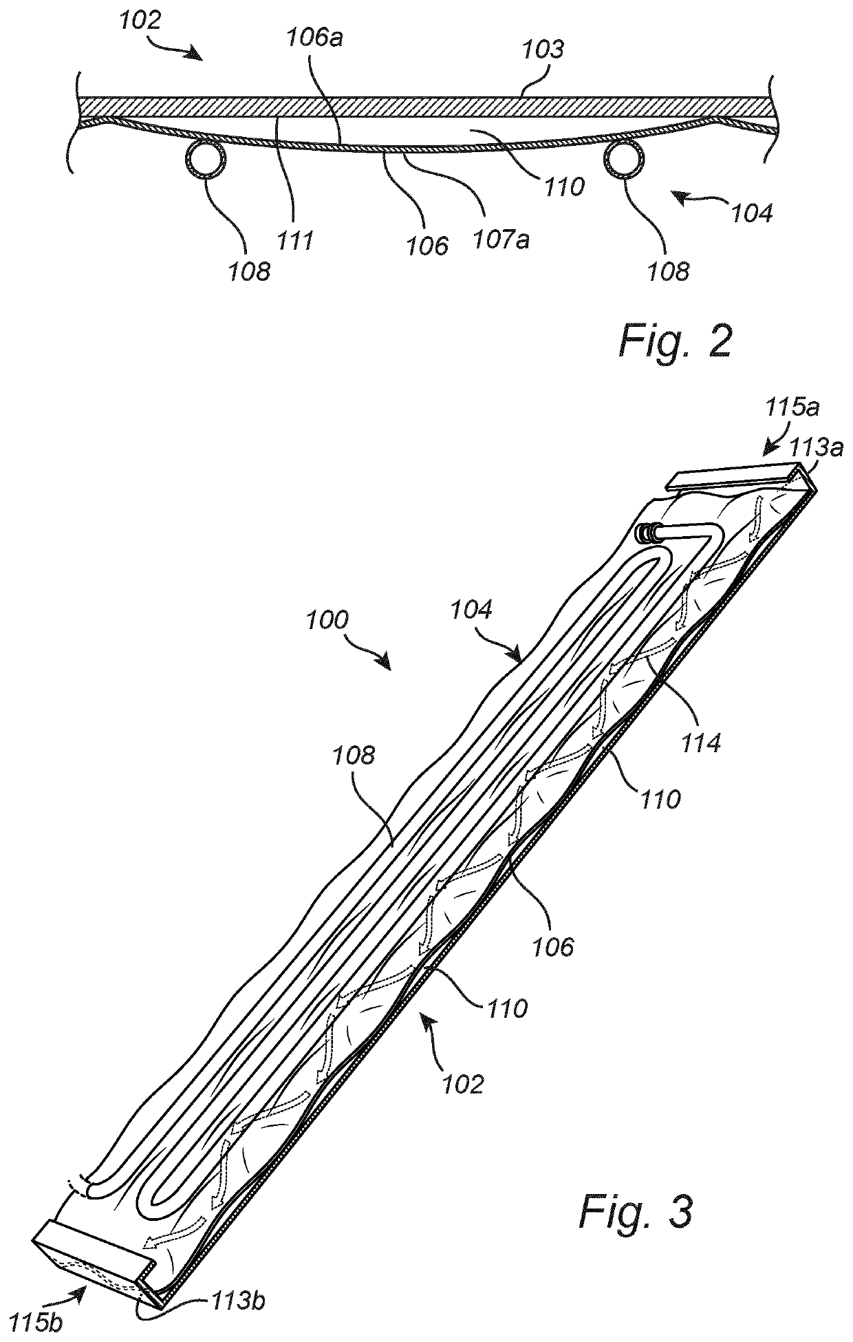
[0054]FIG. 1 schematically illustrates an exploded view of a conceptual hybrid power and heat generating device 100 of the present disclosure. The device 100 comprises a photovoltaic solar power collector 102 configured to collect solar power from solar radiation received on an active side 103 of the photovoltaic solar power collector 102.

[0055]The hybrid power and heat generating device 100 further comprises a heat exchanging unit 104 configured to cool the photovoltaic solar power collector 102....


PUM


Abstract

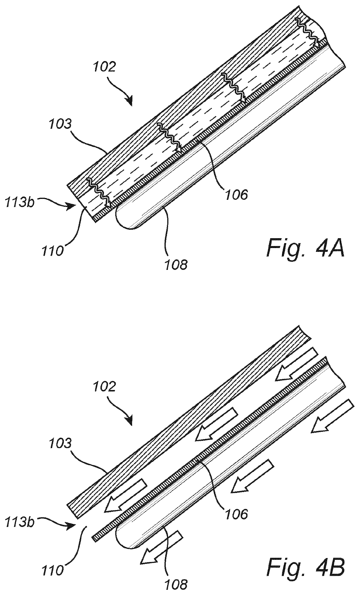
A hybrid power and heat generating device (100) comprising: a photovoltaic solar power collector (102) configured to collect solar power from solar radiation received on an active side (103) of the photovoltaic solar power collector; and a heat exchanging unit (104) configured to cool the photovoltaic solar power collector, which heat exchanging unit includes a cooling plate (106;404;504704) arranged to transfer heat from the photovoltaic solar power collector (102) to a cooling medium. The heat exchanging unit (104) is adapted to transport the cooling medium away from the cooling plate (106;404;504;704) for heat extraction from the cooling medium. The cooling plate (106;404;504;704) is arranged with a gap (110) from a rear side (111) of the photovoltaic solar power collector (102) and the cooling medium is arranged to cool the cooling plate (106;404;504;704) to a temperature which allows water vapor of the ambient air in the gap (110) to condensate into water on the cooling plate (106;404;504;704) in the gap (110). The hybrid power and heat generating device (100) being operable in at least two operation modes; a normal operation mode in which the gap (110) is at least partly filled with condensed water, which condensed water transfers heat from the photovoltaic solar power collector (102) to the cooling plate (106;404;504;704); and a security operation mode in which the gap (110) is filled with air to thereby reduce the heat transfer from the photovoltaic solar collector (102) to the cooling plate (106;404;504;704).

Description

FIELD OF THE INVENTION[0001]The present invention relates to a hybrid power and heat generating device.BACKGROUND OF THE INVENTION[0002]Solar power is one emerging technology for generating environmentally friendly power. Solar power may be collected using photovoltaic devices which directly generate electricity from solar radiation. Another possibility for collecting solar power is to use solar thermal collectors which operate by allowing a fluid to be heated by the solar radiation. The heat from the fluid is subsequently extracted.[0003]There have been prior attempts to combine both photovoltaic devices and solar thermal collectors to form a hybrid solution. WO 2012 / 130429 A2 discloses a conversion device comprising a photovoltaic module and a solar thermal module with a surface element. A channel comprising a gas is arranged between the photovoltaic module and the surface element. By this means thermal energy can be transferred from or through the gas to the surface element.[0004...

Claims


Application Information

Patent Timeline
Patent Type & Authority Applications(United States)
IPC IPC(8): H02S40/44F24S40/55F24S10/30F24S10/50H02S30/10H02S40/42
CPCH02S40/44F24S40/55F24S10/30F24S2080/03H02S30/10H02S40/425F24S10/50Y02E10/44Y02E10/50Y02E10/60
Inventor SAMUELSSON, KENTSTEIER, VILHELM
Owner SAMSTER AB
Learn More