
Assembled constructional reinforced concrete structural member

A technology for building steel bars and concrete components, which is applied in the direction of building components, building reinforcements, building structures, etc., can solve the problems of unsuitable component assembly steel bar connection, difficulty in putting in cold-pressed connection machinery, and affecting assembly construction speed, etc., to achieve Solve the effect of large amount of assembly construction, stable joint reliability and low connection cost

Inactive Publication Date: 2012-09-19
江苏金砼预制装配建筑发展有限公司
View PDF15 Cites 13 Cited by
  • Summary
  • Abstract
  • Description
  • Claims
  • Application Information

AI Technical Summary

Problems solved by technology

Chinese patent CN87201172 pressure cold-pressed connection, but the steel bars of building components are relatively dense, the cold-pressed connection machine is difficult to put in, and it requires multiple people to operate and carry large ultra-high pressure hydraulic equipment, so it is basically not suitable for component assembly steel bar connection
However, there are still some deficiencies. For example, in order to meet the connection strength requirements (effective anchoring of chemical slurry), the length of the connecting sleeve used is relatively long. The diameter of the steel bar is less than 20mm, and the length of the sleeve needs to reach 250mm. , for the connection of a large number of steel bars in prefabricated buildings, the long connecting sleeve is still a considerable expense, and the connection cost is relatively high; secondly, one end of the sleeve connection is cemented with chemical slurry, and its structural strength depends on the chemical adhesive It is only available after curing, and it usually takes about a day for the chemical slurry to cure, so that the component can only have the force bearing capacity after one day of assembly, and can carry out subsequent operations, so it still affects the assembly construction speed, and it is difficult to truly realize the reinforced concrete prefabricated building. quick loading requirements

Method used


Image

  • Assembled constructional reinforced concrete structural member
  • Assembled constructional reinforced concrete structural member
  • Assembled constructional reinforced concrete structural member

Examples


Embodiment 1

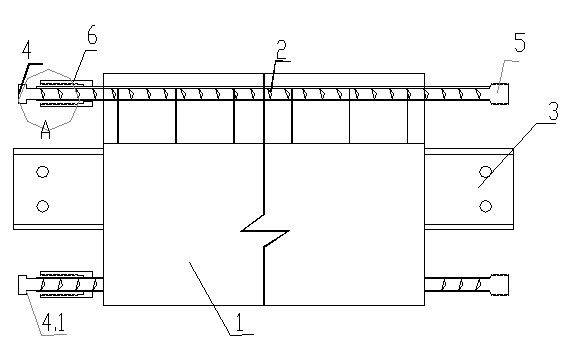
[0030] Embodiment 1: see figure 2 , 6 , the prefabricated concrete beam member of the present invention includes a concrete prefabricated structural beam 1, which is arranged according to the stress design and has a threaded structural steel bar 2 extending out of the concrete end at both ends, such as φ20mm, and the two ends of the concrete beam 1 also have protruding end faces The section steel connecting joint 3. Among them, the threaded structural steel bar 2 protruding from the two ends of the concrete beam has a cylindrical thread head 5 with a thickened side thickness of 8mm (thickened radius, thickened diameter 36mm) and a length of 30mm at one end, and a thickened side thickness of 8mm at the other end. , a cylindrical bolt head 4 with a length of 3 cm, the axial inner end surface 4.1 of the cylindrical bolt head 4 is flat, and a connecting sleeve 6 with a length of 110 mm is set inside the cylindrical bolt head 4. The outer end of the connecting sleeve 6 is an inte...

Embodiment 2

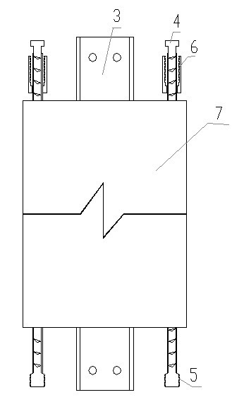
[0031] Example 2: see image 3 , as in Example 1, the prefabricated concrete component is a concrete structural column 7, and the two ends respectively have a section steel joint 3 and a structural steel bar 2 protruding from the concrete end face, wherein the structural steel bar protrudes, and one end is a thickened cylindrical thread head 5, The other end is a thickened cylindrical bolt head 4, the inner end surface of the cylindrical bolt head 4 is flat, and the cylindrical bolt head 4 is sleeved with a connecting sleeve 6, the outer end of the connecting sleeve 6 is an internal thread 6.2, and the inner end is an inner plane Reduction port 6.1 (rotate to hook cylinder bolt head 4).

Embodiment 3

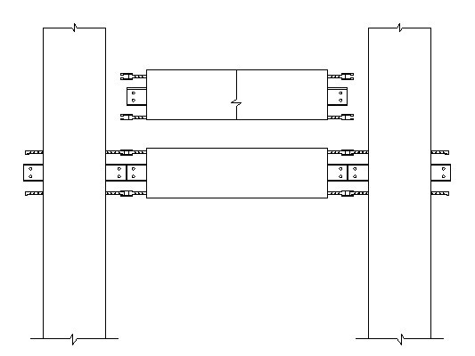
[0032] Embodiment 3: see Figure 4 , as in Example 1, wherein the prefabricated concrete member is a beam-inner thermal insulation wall integrated structure, that is, the upper end is a structural beam 8, and the lower end of the beam is a hollow thermal insulation wall 9, and the structural steel bar heads extending out of the concrete at both ends of the beam are as in the embodiment 1 described.


PUM


Abstract

The invention relates to an improved assembled constructional reinforced concrete structural member which is characterized in that the connecting end of the concrete structural member extends to form a concrete structure or connecting reinforcement; and the head of the concrete structural member is a cylindrical bolt head and / or a cylindrical thread head which is thickened in the radial direction and has the peripheral thickness of more than or equal to 4mm; the inner side of a bolt head at the cylindrical bolt head end is preliminarily sleeved with a connecting sleeve, of which the outer end is an internal thread and the inner end is a neck. During structural member assembly and reinforcement connection, only the connecting sleeve is needed to be moved outwards along the axial direction and rotated to be screwed together with the cylindrical thread head connected to the other end of the connecting sleeve, so that sleeve connection can be used for locating the reinforcement connection of the assembled concrete structural member, stress strength is achieved after the connection is finished, the construction speed for assembling and connecting the concrete structural member is greatly increased, the strength of a joint is greater than that of reinforcement base metal, the joint is stable in reliability and is not influenced by personal factors, only one connecting sleeve is needed, and therefore, smaller length of only 60-100mm is needed, materials are saved, the connection cost is low, and the defects of large construction workload for assembling an assembled reinforced concrete building in situ, labor waste for in-situ assembly construction, low speed and instable quality are overcome.

Description

technical field [0001] The present invention is an improvement to reinforced concrete components of prefabricated buildings, and in particular relates to a prefabricated building which is suitable for on-site positioning and assembly of components, does not need to be welded for connection of steel bars of structural parts, quick on-site assembly, reliable connection and good stability, and low cost of steel bar connection Reinforced concrete components. Background technique [0002] Reinforced concrete prefabricated buildings, because the concrete components are prefabricated in the factory and transported to the construction site for assembly and assembly, it has the advantages of saving building materials, less on-site construction, quick construction, good quality assurance and construction environmental protection, and can realize the industrialization of the factory. gradually gained attention and promotion. However, the assembly and connection of building structural ...

Claims


Application Information

Patent Timeline
IPC IPC(8): E04B1/41E04C5/01E04C5/16
Inventor 张吉华张晨
Owner 江苏金砼预制装配建筑发展有限公司
Learn More