
Reinforcing steel bar assembly type structural reinforcing steel bar for building, connecting head part molding method and connecting head part molding mold

A forming method and construction technology, applied in building components, building structures, construction, etc., can solve problems such as the difficulty of putting in cold-pressed connection machinery, reducing the tensile strength of steel bars, and low efficiency of hot forging thickening, and achieve joints Stable reliability, improved construction speed, and low production cost

Inactive Publication Date: 2012-07-25
江苏金砼预制装配建筑发展有限公司
View PDF11 Cites 6 Cited by
  • Summary
  • Abstract
  • Description
  • Claims
  • Application Information

AI Technical Summary

Problems solved by technology

Chinese patent CN87201172 pressure cold-press connection, for building components, the steel bars are relatively dense, and the cold-press connection machine is difficult to put in, and it requires multiple people to operate and carry large ultra-high pressure hydraulic equipment, so it is basically not suitable for component assembly steel bar connection
In Chinese patents CN2102325, CN1746452, CN101624854, CN102322059, etc., the steel bars are connected by a sleeve connection. In short, although this is suitable for densely reinforced construction, there is no limit to the three-dimensional space, but the prerequisite is that the reinforced steel (component) must be able to rotate and / or move axially
For example, the screw sleeve connection with both ends of the connecting steel bar being threaded can only be used for the rotatable and axially moving connection of the steel bar, but for the finished concrete member, it is a positioning assembly during assembly, which can neither rotate nor move axially. , so it is not suitable. For this reason, there is no report in the prior art that the steel bar connection of concrete members adopts screw sleeve connection.
Cold heading thickens the head of the steel bar. For thicker threaded steel bars used in construction, it is difficult to obtain a thickened edge thickness greater than 3mm by cold heading. If the diameter is increased, not only a large cold heading machine is required, but also the head of the steel bar will be damaged. Excessive deformation will change the material and reduce the tensile strength of the steel bar. Therefore, in order to obtain a larger thickening similar to the bolt head in cold heading, the diameter of the steel bar should not exceed 10mm; Equipped with a heating furnace and a hot section machine, it is not suitable for the concrete component pouring site, and the thickening efficiency of hot forging is low, resulting in increased thickening costs, which is not actually adopted by the construction industry

Method used


Image

  • Reinforcing steel bar assembly type structural reinforcing steel bar for building, connecting head part molding method and connecting head part molding mold
  • Reinforcing steel bar assembly type structural reinforcing steel bar for building, connecting head part molding method and connecting head part molding mold
  • Reinforcing steel bar assembly type structural reinforcing steel bar for building, connecting head part molding method and connecting head part molding mold

Examples


Embodiment

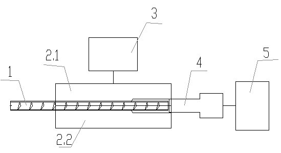
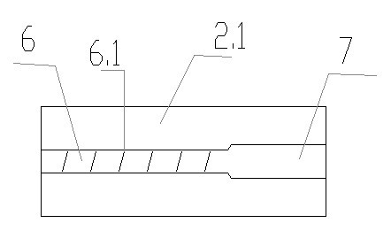
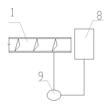
[0027] Example: see Figure 1-4 First, the end of the threaded steel bar 1 (such as 20mm in diameter, depending on the length of the component) and the different material electrode (copper electrode) 8, and the arc heating device (such as a steel bar butt welding machine transformer) composed of a resistance or an arc heating transformer 9, Heat the head to 600-800°C (redness). Then put it into the mating mold 2.1 and 2.2 mold cavities, the end of the steel bar protrudes from the cavity of the threaded section by 9cm, the upper and lower molds are combined to clamp the steel bar 1 by the compression cylinder 3, and the axial extrusion cylinder 5 is started to push the extrusion at the same time The plug 4 compresses the protruding thread groove steel bar from 9cm to 3cm, and the plastic deformation caused by the extrusion force makes the steel bar axially shorten and thicken under the limit of the mold cavity (the compression amount reaches 6cm, and a cylindrical bolt head wit...


PUM

PropertyMeasurementUnit
Lengthaaaaaaaaaa
Diameteraaaaaaaaaa

Abstract

The invention relates to an improvement on a reinforcing steel bar assembly type structural reinforcing steel bar for a building, also relates to a reinforcing steel bar head part molding method and a reinforcing steel bar head part molding mold. The reinforcing steel bar is characterized in that cylindrical bolt heads and / or cylindrical thread heads are arranged at the two end parts of the reinforcing steel bar, the radial thickening ring edges of the cylindrical bolt heads and / or cylindrical thread heads are more than or equal to 4mm, wherein the axial inner end surfaces of the cylindrical bolt heads are planes, and connecting sleeves are sheathed at the inner sides of the cylindrical bolt heads in advance, the outer ends of the connecting sleeves are inner threads, and the inner ends of the connecting sleeves are inner plane contraction ports. The molding method is implemented as follows: the single end is molded into a cylinder through the steps that the head part is heated until the color of the head part is red at least, then the heated head part is placed in a clamping and thickening limitation mold to be clamped tightly by external force, and the end surface of the heated head part is extruded and thickened to be full of the mold. The mold adopts a folding mold with two symmetrical sections, the folding surfaces are respectively provided with a semi-circular groove, the diameter of which is basically equal to that of the reinforcing steel bar, the concave surface of the semi-circular groove is provided with concave threads basically identical to the threads of the reinforcing steel bar, and a thickened semi-circular groove is arranged at one end of the semi-circular groove, wherein the diameter of the thickened semi-circular groove is more than or equal to 8mm. when a casted concrete member is used for assembling the reinforcing steel bar, the sleeves are adopted for connection, plenty of welding connection amount are omitted, so that the requirement of low cost of the building can be met.

Description

technical field [0001] The invention is an improvement to the structural steel bars used in reinforced concrete assembly buildings, and in particular relates to a structural steel bar which can be connected with a sleeve for assembling concrete components, a forming method and a mold for the head of the steel bar. Background technique [0002] Reinforced concrete prefabricated building concrete components usually adopt threaded steel bars, and the diameter is about 12-32mm depending on the force. When the concrete components are assembled and connected, they are first positioned and fixed by the protruding concrete end face steel joints, and then the steel bars are welded one by one. Connect and pour concrete at the end. Due to the structural requirements (tension, bending and complex stress) of reinforced concrete members, the number of stressed structural steel bars in the concrete is relatively large, such as the connection between beams and beams, at least 4 steel bars, ...

Claims


Application Information

Patent Timeline
IPC IPC(8): E04C5/02E04C5/16B21F5/00
Inventor 张吉华张晨
Owner 江苏金砼预制装配建筑发展有限公司
Learn More