Cylindrical hole sealing bag
A sealing bag, cylindrical technology, used in sealing/sealing, gas discharge, safety devices, etc., can solve the problems of air leakage, inability to effectively complete the sealing of the sealing section, inconvenient to use, etc., and achieve convenient use. Effect
- Summary
- Abstract
- Description
- Claims
- Application Information
AI Technical Summary
Problems solved by technology
Method used
Image

Examples
Embodiment 1
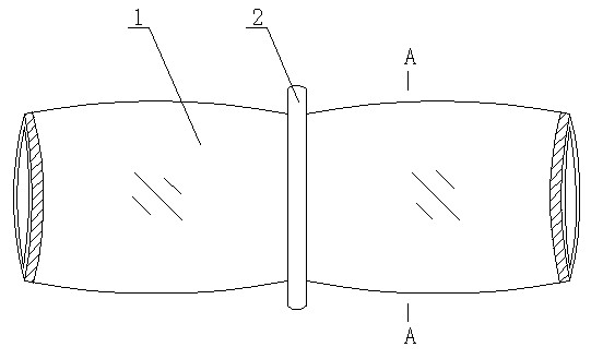
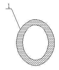
[0024] figure 1 It is a structural schematic diagram of Embodiment 1 of the present invention, figure 2 for figure 1 A-A sectional view, as shown in the figure, the cylindrical sealing bag of the present embodiment includes a bag body 1, the bag body 1 is a sandwich bag body composed of an inner layer and an outer layer, and the bag body 1 is a cylinder Shape, the middle part of the bag body 1 is provided with an openable and closable partition device 2, the partition device 2 divides the bag body 1 into two parts isolated from each other, and the interlayers of the two parts bag body 1 are filled one by one. Two components of the foam material.
[0025] In this embodiment, the partition device 2 is a sealing clip clamped on the outer surface of the bag body 1; of course, the partition device can also be in other openable and closable structural forms, such as: the partition device is a self-heated press in the middle of the bag body. Isolation belt, when in use, punch out...
Embodiment 2
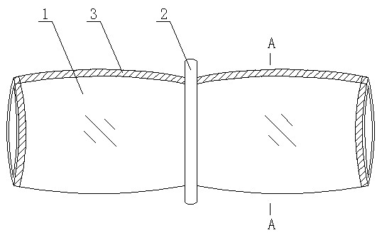
[0030] image 3 It is a structural schematic diagram of Embodiment 2 of the present invention, Figure 4 for image 3 A-A sectional view of A-A, as shown in the figure, the cylindrical sealing bag of this embodiment is different from that of Embodiment 1 in that: in this embodiment, an inner wall of the bag body 1 is provided along the generatrix of the bag body 1. The thermocompression seam 3 formed by thermocompression bonding of the layer and the outer layer.
[0031] The cylindrical sealing bag of this embodiment is provided with hot pressing seams 3 along the bus line of the bag body 1, which is conducive to the final bursting of the bag body 1 after the foaming material in the interlayer of the bag body 1 is foamed, so that the sealing effect is better; of course , because the cylindrical bag body 1 is completely wrapped around the extraction pipe, even if the sealing bag is broken and there is an obstacle, the sealing requirement can be met.
Embodiment 3
[0033] Figure 5 It is a structural schematic diagram of Embodiment 3 of the present invention, Image 6 for Figure 5 A-A cross-sectional view of A-A, as shown in the figure, the cylindrical sealing bag of this embodiment is different from that of Embodiment 1 in that: in this embodiment, there are two holes formed by the bag body 1 along the generatrix of the bag body 1. The thermocompression seam 3 formed by thermocompression bonding of the inner layer and the outer layer.
[0034] The cylindrical sealing bag of this embodiment is provided with hot pressing seams 3 along the bus line of the bag body 1, which is conducive to the final bursting of the bag body 1 after the foaming material in the interlayer of the bag body 1 is foamed, so that the sealing effect is better; of course , because the cylindrical bag body 1 is completely wound around the extraction pipe, it can ensure that the hole sealing requirement can be met even when the hole sealing bag is broken and there ...
PUM
 Abstract
Description
Claims
Application Information
 - R&D
- Intellectual Property
- Life Sciences
- Materials
- Tech Scout
- Unparalleled Data Quality
- Higher Quality Content
- 60% Fewer Hallucinations
Browse by: Latest US Patents, China's latest patents, Technical Efficacy Thesaurus, Application Domain, Technology Topic, Popular Technical Reports.
© 2025 PatSnap. All rights reserved.Legal|Privacy policy|Modern Slavery Act Transparency Statement|Sitemap|About US| Contact US: help@patsnap.com