
Mobile counterweight type pumping unit

A technology of counterweight and pumping unit, which is applied in the direction of machine/engine, liquid variable capacity machinery, mechanical equipment, etc., can solve problems such as energy waste, and achieve the effect of energy saving and simple structure

Inactive Publication Date: 2012-09-19
樊红海
View PDF4 Cites 10 Cited by
  • Summary
  • Abstract
  • Description
  • Claims
  • Application Information

AI Technical Summary

Problems solved by technology

[0004] The purpose of the present invention is to provide a mobile counterweight pumping unit. This pumping unit aims at the shortcoming of energy waste in the existing crank balanced pumping unit. Oil, to achieve the purpose of energy saving

Method used

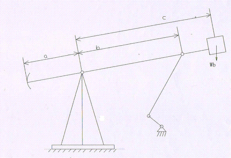

Image

  • Mobile counterweight type pumping unit
  • Mobile counterweight type pumping unit
  • Mobile counterweight type pumping unit

Examples


Embodiment Construction

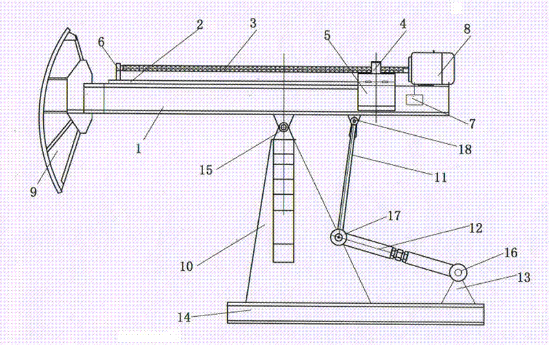
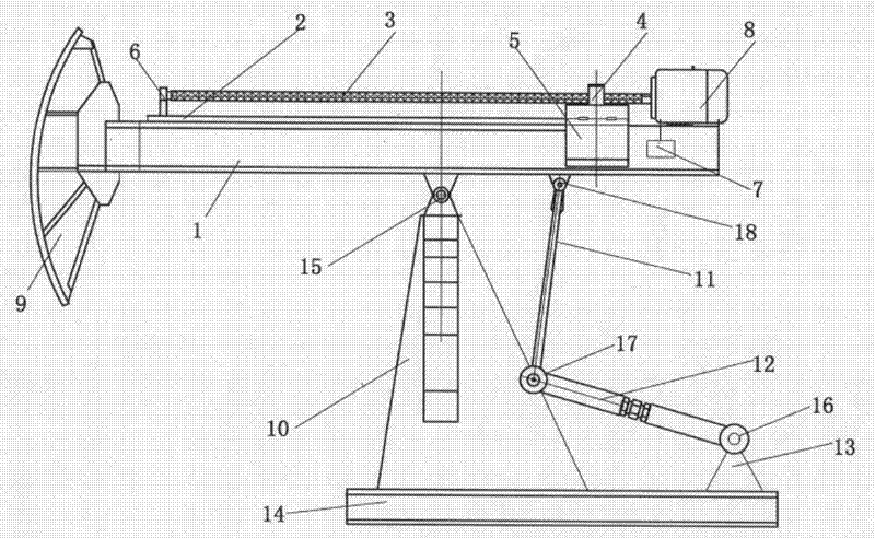
[0055] The mobile counterweight type pumping unit comprises a counterweight type balance mechanism, a tripod 10, a crank link mechanism and a frame 14.

[0056] The counterweight type balance mechanism includes a beam 1, two identical slideways 2, a reciprocating lead screw 3, two identical counterweights 5, a variable frequency motor 8 and a donkey head 9.

[0057] The frequency conversion motor 8 is fixed on the right side of the upper end face of the beam 1, and the frequency conversion motor 8 is connected with the reciprocating wire through the shaft coupling.

[0058] -3-

[0059] The right end of bar 3 is connected, and the left end of reciprocating leading screw 3 is supported on the left side of the upper end surface of swimming beam 1 by leading screw support 6 . Slideways 2 are respectively fixed on both sides of the beam 1 .

[0060] A screw nut 4 is installed on the reciprocating lead screw 3, and two identical counterweights 5 are fixed on the screw nut 4, and ...


PUM


Abstract

A mobile counterweight type pumping unit comprises a counterweight type balancing mechanism, a triangular support, a crank and connecting rod mechanism and frame. The counterweight type balancing mechanism comprises a walking beam, two slideways, a reciprocating screw rod, two counterweight blocks, a variable frequency motor and a horsehead. The variable frequency motor is fixed on the right of the upper end face of the walking beam and is connected to the right end of the reciprocating screw rod. The left end of the reciprocating screw rod is supported on the left of the upper end face of the walking beam through a screw rod bearing. The slideways are fixed on two sides of the walking beam. A nut is fitted on the reciprocating screw rod. Two identical counterweights are fixed onto the nut and are slidably fitted with the slideways respectively. A balancing block is fixed at the right end of the walking beam. The upper end of the triangular support is connected with the walking beam through a triangular support shaft. The upper end of a connecting rod is connected with the walking beam through an upper shaft. The lower end of a crank is connected with a shaft seat through a crankshaft. The lower end of the triangular support and the shaft seat are fixed onto the frame respectively. By replacing an original balancing block and a reducer with the counterweights and adding the balancing block onto the walking beam, the mobile counterweight type pumping unit is simple in structure and energy-saving.

Description

technical field [0001] The invention belongs to the field of oil pumping units, in particular to a mobile counterweight type oil pumping unit which uses a mobile counterweight to realize oil pumping. Background technique [0002] At present, crank balance pumping units are widely used in oil fields. In actual operation, the work done by the upstroke is to lift the weight of the rod, pump, liquid column, etc. and overcome friction, while the work done by the downstroke is only the work of the rod, pump, etc. weight. This shows that in the actual operation of the pumping unit, the work required for the up and down strokes is different, which forms a waste of energy. For the weight of the rod, pump, etc., this part of the weight can be used in the beam The way of adding a balance block on the top is balanced to achieve energy saving effect. At the same time, in the working process of the original crank balanced pumping unit, a large part of the work of the motor is to drive t...

Claims


Application Information

Patent Timeline
IPC IPC(8): E21B43/00F04B47/14
Inventor 樊红海
Owner 樊红海
Learn More