Double-acting hydraulic ejecting type vacuumizing and compressing device of double cylinders

A compression device, injection-type technology, applied in the field of machinery, can solve the problem that the compression capacity or vacuuming capacity of the integrated piston vacuum pump and piston air compressor cannot meet the requirements of practical applications, and the piston vacuum pump and piston air compressor cannot meet the actual application requirements. Problems such as the integration of the compressor, the compression capacity of the all-in-one machine or the lack of vacuuming capacity, etc., to achieve the effect of upper air or fast air extraction, simple structure, and tight sealing

Inactive Publication Date: 2012-09-19
陈人德 +1
View PDF7 Cites 11 Cited by
  • Summary
  • Abstract
  • Description
  • Claims
  • Application Information

AI Technical Summary

Problems solved by technology

[0004] It can be seen from the above-mentioned general technology that although the piston vacuum pump and the piston air compressor use the same motion principle, there is no equipment that integrates the piston vacuum pump and the piston air compressor in the existing market. It is difficult to solve the following problems:
[0005] 1. The motor is used as the power, the motor is set on one side, and it is also transmitted through the transmission mechanism in the middle, so that the compression capacity or vacuuming capacity of the integrated piston vacuum pump and piston air compressor cannot meet the requirements of practical applications. Not a substitute for multi-stage compression or vacuuming
[0006] 2. Due to the relatively large force on the piston due to air compression and / or vacuuming, the sealing ring on the piston has to bear a large pressure, resulting in poor sealing effect, so that the compression capacity or vacuuming capacity of the all-in-one machine cannot reach Practical application requirements

Method used


Image

  • Double-acting hydraulic ejecting type vacuumizing and compressing device of double cylinders
  • Double-acting hydraulic ejecting type vacuumizing and compressing device of double cylinders
  • Double-acting hydraulic ejecting type vacuumizing and compressing device of double cylinders

Examples


Embodiment Construction

[0026] The following are specific embodiments of the present invention, and further describe the technical solution of the present invention in conjunction with the accompanying drawings, but the present invention is not limited to these embodiments.

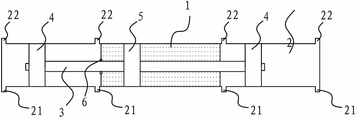
[0027] Such as figure 1 As shown, the vacuuming and compression device of the double-acting hydraulic injection type double cylinder includes a hydraulic cylinder body 1, a cylinder body 2, a double output rod 3, a cylinder piston 4, and a hydraulic cylinder piston 5, as well as a detection mechanism and hydraulic automatic control The mechanism is used to realize the integrated function of air compression and vacuum pumping, and can perform air compression, vacuum pumping, and air compression and vacuum pumping at the same time, so as to realize three functions of one machine and meet the requirements of actual use.

[0028]Specifically, there are two cylinder blocks 2, which are respectively symmetrically connected to the two ...


PUM


Abstract

The invention provides a double-acting hydraulic ejecting type vacuumizing and compressing device of double cylinder and belongs to the technical field of machinery. The double-acting hydraulic ejecting type vacuumizing and compressing device solves the problem that compressing capacity or vacuumizing capacity of an all-in-one machine of a piston type vacuum pump and a piston type air compressor cannot achieve the actual application requirements and comprises a hydraulic cylinder body and two cylinder bodies, wherein the cylinder bodies are respectively connected with two ends of the hydraulic cylinder body, a hydraulic cylinder piston is arranged in the hydraulic cylinder body, a double-extending rod with two ends respectively extending out of the hydraulic cylinder body and entering the cylinder bodies is fixed on the hydraulic cylinder piston, cylinder pistons fixed on corresponding end portions of the double-extending rod are respectively arranged in the two cylinder bodies, and an air inlet valve and an air outlet valve for communicating a cavity of the cylinder are respectively arranged on the end portions of the cylinder bodies on two sides of each cylinder piston. The double-acting hydraulic ejecting type vacuumizing and compressing device can integrate air compressing and vacuumizing, has three functions in one machine and can achieve the requirements for actual using.

Description

technical field [0001] The invention belongs to the technical field of machinery and relates to a double-acting hydraulic injection type double-cylinder vacuuming and compression device. Background technique [0002] The machine that draws gas from the equipment to make the inside of the equipment vacuum is called a vacuum pump. Vacuum pumps can be roughly divided into reciprocating vacuum pumps, rotary vacuum pumps and jet vacuum pumps according to different movement modes. Among them, the reciprocating vacuum pump, also known as the piston vacuum pump, pumps air by periodically changing the working volume of the cylinder. The piston vacuum pump only works in the cylinder chamber on one side of the piston during the pumping process, while the cylinder chamber on the other side of the piston is in an idle state. It is a single-acting structure with low working efficiency. The working air pressure is not uniform, so that the seal on the piston is subjected to a large force ...

Claims


Application Information

Patent Timeline
Patent Type & Authority Applications(China)
IPC IPC(8): F04B35/02
Inventor 陈人德陈理明陈纪舣
Owner 陈人德
Why Eureka
Try Eureka