Cooling device for drive train

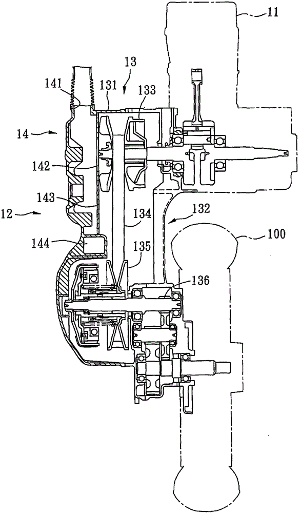
A transmission system and cooling device technology, applied in the direction of transmission, gear lubrication/cooling, and dispersed particle filtration, etc., can solve problems such as damage, wear of the transmission group 132, and influence on appearance design, and achieve high versatility and avoid wear Effect

Active Publication Date: 2015-11-25
KYMCO
View PDF4 Cites 0 Cited by
  • Summary
  • Abstract
  • Description
  • Claims
  • Application Information

AI Technical Summary

Problems solved by technology

[0005] Utilize the air inlet 141 of this cooling device 14 to introduce air, then blow to the speed change group 132 that is arranged in this transmission case 131 through the perforation 142 on this wind deflector 143, finally discharge by this exhaust port 144, so although The transmission group 132 can be cooled, but when the air enters the transmission case 131 through the air inlet 141 to cool the transmission case 132, dust or foreign matter will also be brought into the transmission case 131 together. Cause the wearing and tearing of this shift group 132 even damage
[0006] refer to figure 2 , in order to improve the above-mentioned shortcoming, China Taiwan Announcement No. I297311 " the cooling air introduction structure of the transmission case of scooter motorcycle " invention patent is to set up a shroud 15 outside this transmission case 131, and a cover this deflector The cover 15 and the introduction member 16 of the transmission case 131 utilize the filter element 151 of the shroud 15 to filter the dust or foreign matter in the air introduced by the introduction member 16, effectively preventing the dust or foreign matter in the air from causing the transmission group to 132 is worn or even damaged, but adding the shroud 15 and the introduction member 16 outside the transmission case 131 will not only increase the lateral volume of the scooter motorcycle 1 and affect the overall handling, but will also affect the overall design

Method used


Image

  • Cooling device for drive train
  • Cooling device for drive train
  • Cooling device for drive train

Examples


Embodiment Construction

[0062] The aforementioned and other technical contents, features and effects of the present invention will be clearly presented in the following detailed description of two preferred embodiments with reference to the drawings.

[0063] Before the present invention is described in detail, it should be noted that in the following description, similar elements are denoted by the same reference numerals.

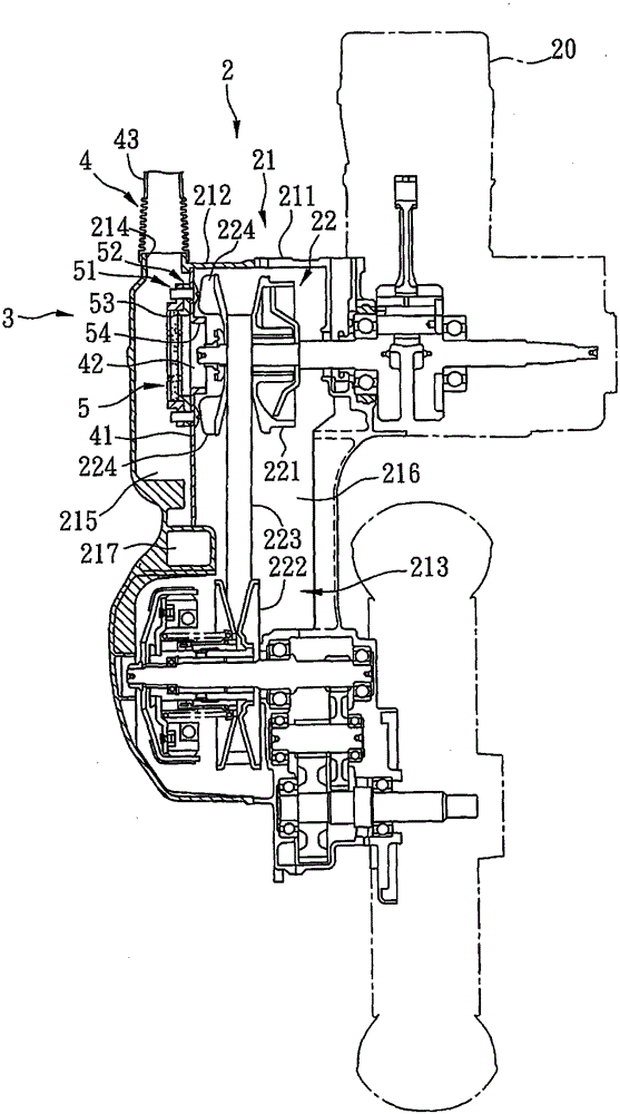
[0064] refer to image 3, the first preferred embodiment of the cooling device 3 of the transmission system of the present invention is applicable to the transmission system 2 of a motorcycle. The transmission system 2 includes a transmission box 21 for transmitting the power of an engine 20 and forming an air inlet 214 and an air outlet 217 , and a transmission unit 22 disposed in the transmission box 21 .

[0065] The transmission box 21 has a transmission box 211 and a transmission cover 212 that cooperate with each other to define an accommodating space 213 , the air inlet ...


PUM


Abstract

Provided is a cooling device of a transmission system. The transmission system comprises a transmission case with an air inlet and a transmission unit arranged in the transmission case. The cooling device comprises a separation unit and a filter unit, the separation unit comprises a separation plate arranged in the transmission case and provided with an opening, the separation plate separates the transmission case into an air inlet portion communicated with the air inlet and a containing portion containing the transmission unit, and the opening is communicated with the air inlet portion and the containing portion. The filter unit is arranged on the separation plate and covers on the opening, so that the filter unit can filter impurities in air flowing from the air inlet portion to the containing portion to avoid abrasion and damage to the transmission unit, can avoid increase of side direction volume to maintain good control, and has no influence on appearance design of the transmission system.

Description

【Technical field】 [0001] The invention relates to a cooling device, in particular to a cooling device for a transmission system. 【Background technique】 [0002] refer to figure 1 , the existing scooter motorcycle is to input the oil gas mixed with air and fuel oil into an engine 11 to ignite and explode to generate power, and then utilizes a transmission system 12 to drive a wheel 100 by transmitting power. The transmission system 12 includes a transmission device 13 for transmitting the power of the engine 11 , and a cooling device 14 for cooling the transmission device 13 . [0003] The transmission device 13 has a transmission box 131 , and a transmission set 132 disposed in the transmission box 131 to transmit the power generated by the engine 11 to the wheels 100 . The shifting group 132 includes a drive pulley 133 driven by the engine 11, a passive pulley 134 spaced apart from the drive pulley 133, a belt 135 covering the drive pulley 133 and the drive pulley 134, an...

Claims


Application Information

Patent Timeline
Patent Type & Authority Patents(China)
IPC IPC(8): F16H57/04F16H7/02B01D46/30
Inventor 刘承恩周信宏
Owner KYMCO
Why Eureka
Try Eureka