
Spot cutting imaging system

An imaging system and light spot technology, which is applied in the direction of light source fixation, lighting device, and lighting device parts, etc., can solve the problems of limited use of computer lights and limited effect of computer light spot patterns, so as to enrich the effect of light spot patterns and satisfy the The needs of the spot modeling effect, the effect of simple structure

Active Publication Date: 2014-10-29
GUANGZHOU HAOYANG ELECTRONICS CO LTD
View PDF3 Cites 4 Cited by
  • Summary
  • Abstract
  • Description
  • Claims
  • Application Information

AI Technical Summary

Problems solved by technology

[0003] Since the gobo wheel has a certain volume and mass, the usage on computer lights is limited, resulting in limited effect of spot patterns on computer lights.

Method used


Image

  • Spot cutting imaging system
  • Spot cutting imaging system
  • Spot cutting imaging system

Examples


Embodiment Construction

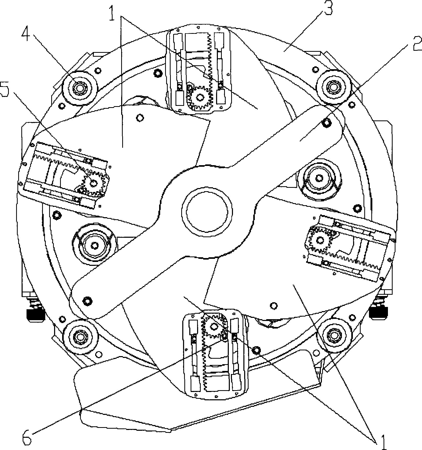
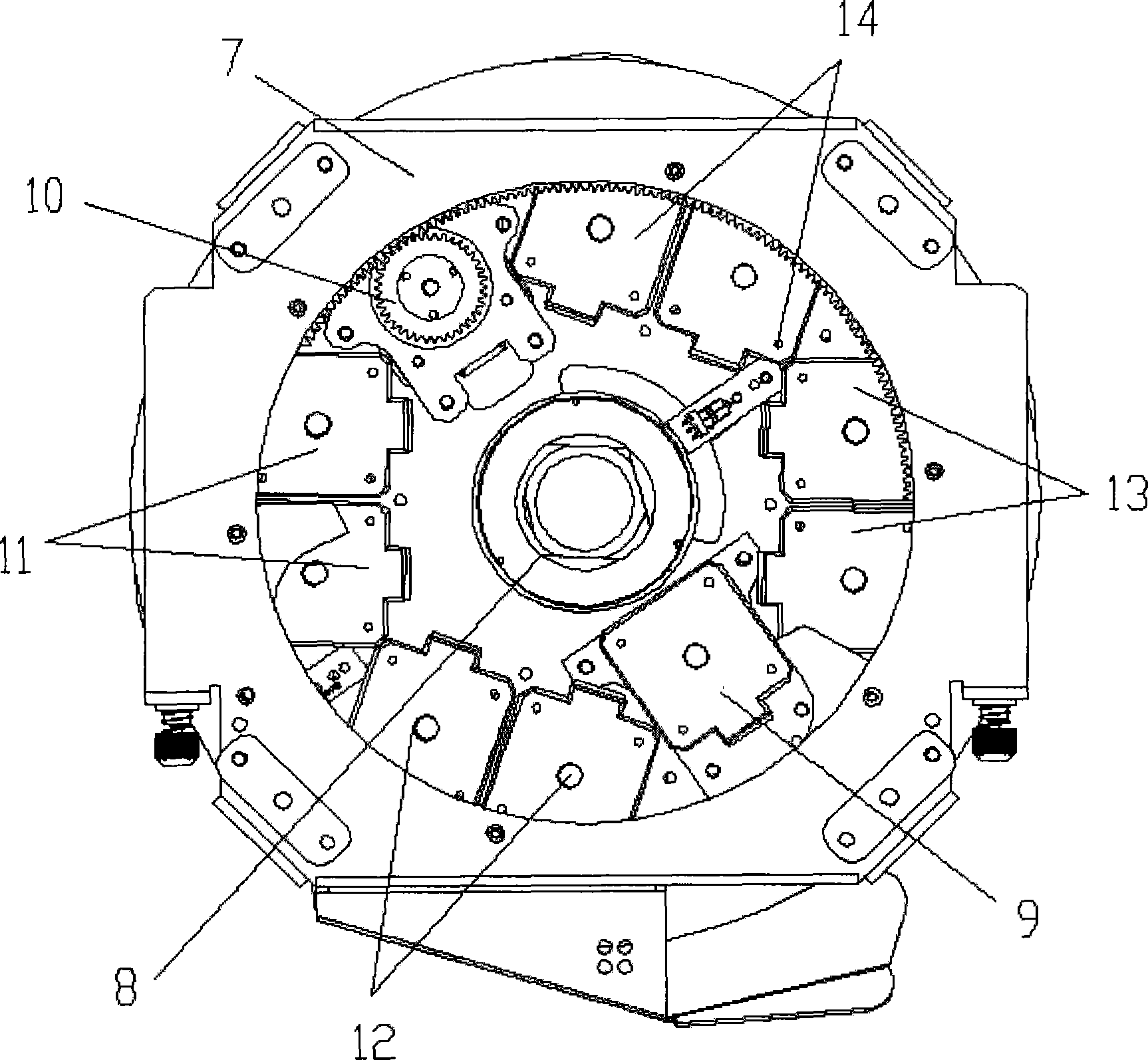
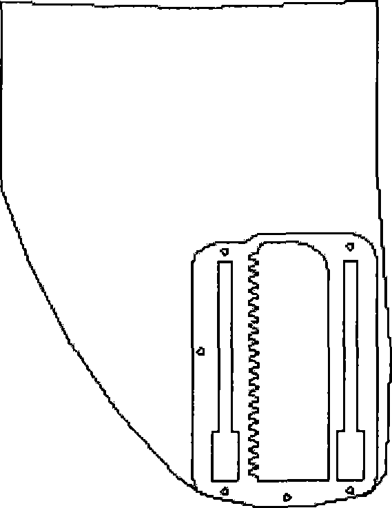
[0026] The invention relates to a light spot cutting imaging system used on a stage lamp. According to an exemplary embodiment of the present invention, as attached figure 1 And attached figure 2 As shown, include: for example 4 fan-shaped light cutting slices (1), grating (8), motor (9), (10), (11), (12), (13), (14) etc. attached image 3 It is a schematic diagram of a light-slicing sheet structure of the present invention. However, obviously, those skilled in the art can understand that the light cutting sheet (1) can not only be fan-shaped, but also can be made into any shape according to actual needs.

[0027] as attached figure 1 And attached figure 2 Shown, the sheet metal support (7) that has rotating wheel (4) is set at the inscribed square four vertices of fixed sheet metal, and rotating wheel (4) is engaged with the chassis of disc (3), and in motor (10) Driven to realize the rotation of the disc (3). The swing of the motor (10) can be effectively blocked by...


PUM


Abstract

The invention relates to an imaging system for cutting light spots applied to a stage lamp. The imaging system comprises a plurality of metallic light-cutting sheets which are not in contact with each other, an elastic grating and a plurality of motors for driving the light-cutting sheets or grating to act through gears. The light-cutting sheets are driven to coordinately act by the motors through the gears, so that light-transmitting ports in any shape and direction are realized; light beams are emitted through the light-transmitting ports and are formed into a corresponding light spot pattern; and the light spots are adjusted through the contraction of the grating. The imaging system for cutting light spots solves the problem that various pattern effects cannot be achieved because the light spots cannot be cut by the traditional stage lamp.

Description

technical field [0001] The invention relates to the field of stage lights, in particular to a light spot cutting imaging system for stage lights. Background technique [0002] At present, the change of the spot pattern of the computer light in the stage lighting industry basically depends on the gobo wheel, and the number of the gobo wheel determines the number of the spot pattern of the computer light, which has great limitations. [0003] Since the gobo wheel has a certain volume and mass, the usage amount on the computer light is limited, which leads to the limitation of the spot pattern effect of the computer light. [0004] The light spot cutting imaging system of the present invention can realize the light opening of any shape through the cooperation of the light cutting sheet, and the light beam is projected out through the light opening to form a corresponding spot pattern, and the size of the light spot can be adjusted through the contraction of the grating, thereby...

Claims


Application Information

Patent Timeline
Patent Type & Authority Patents(China)
IPC IPC(8): F21V14/08
Inventor 蒋伟楷
Owner GUANGZHOU HAOYANG ELECTRONICS CO LTD
Learn More