Vacuum heating device for insulating oil

A technology of vacuum heating and insulating oil, which is applied to water heaters, fluid heaters, lighting and heating equipment, etc., and can solve the problems of insulating oil cracking, high temperature, and different flow rates of insulating oil

Inactive Publication Date: 2012-09-19
WEIFANG POWER SUPPLY OF SHANDONG ELECTRICPOWER CORP +1
View PDF5 Cites 1 Cited by
  • Summary
  • Abstract
  • Description
  • Claims
  • Application Information

AI Technical Summary

Problems solved by technology

This heating device has the following defects: First, the temperature on the surface of the electric heating tube is several hundred degrees. The flow rate of the insulating oil passed is different, and there will be a dead zone of oil flow at the dead corner of the baffle and at both ends, and there will also be local high temperature in this area; the above-mentioned first and second defects will cause severe cracking of the insulating oil, affecting Oil quality after heating
Third, in order to prevent the surface temperature of the isolation tube from being too high, it is necessary to limit the power density per unit area of ​​the isolation tube surface to less than 1.5W / cm2, which limits the total power of a single electric heating tube, resulting in an increase in the number of electric heating tubes. The entire heating device is bulky
The third defect will cause inconvenient transportation of the device and add unnecessary manpower and material resources to the on-site work

Method used


Image

  • Vacuum heating device for insulating oil
  • Vacuum heating device for insulating oil

Examples


Embodiment Construction

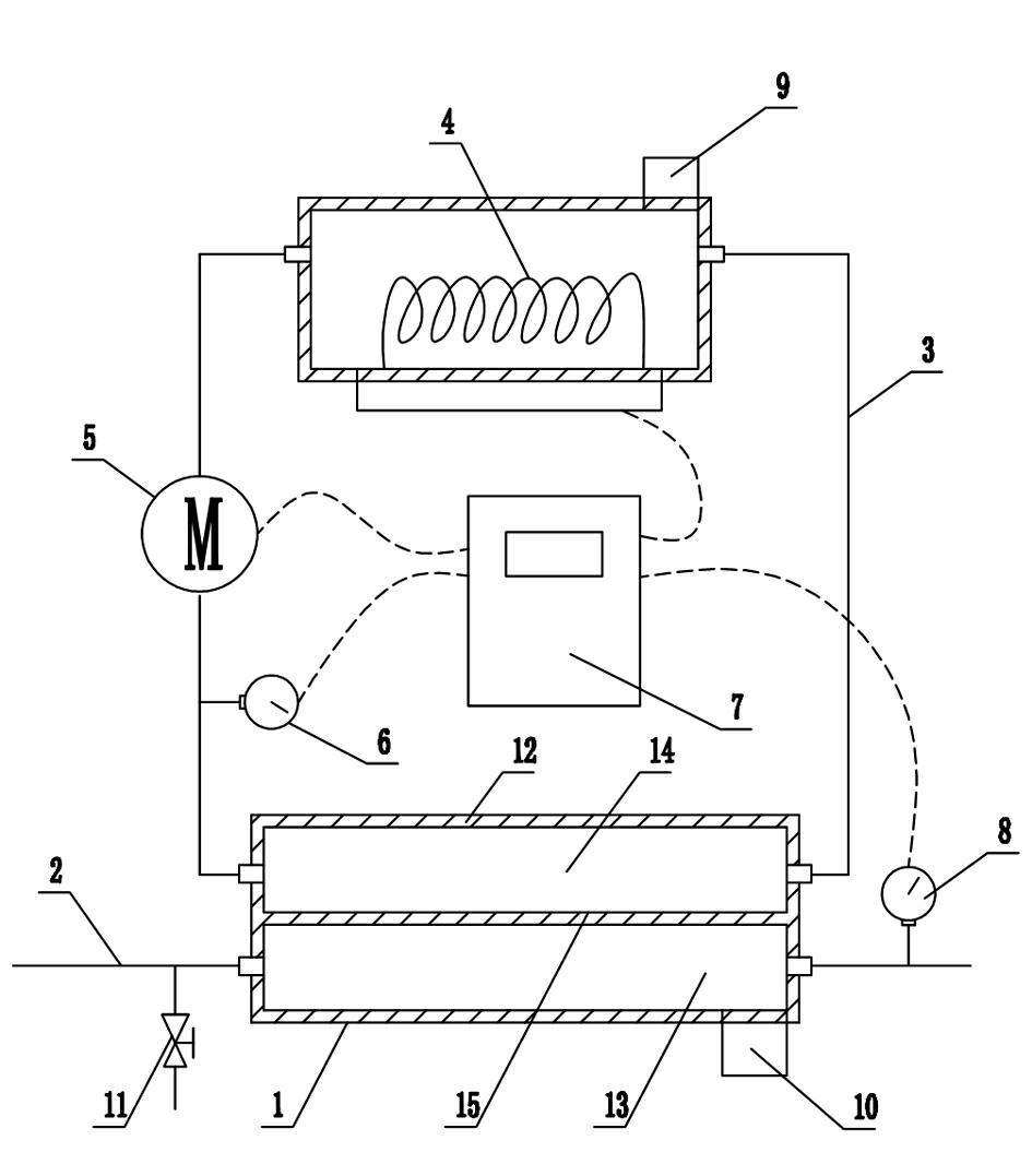
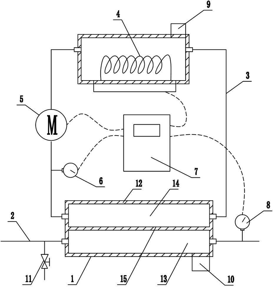
[0023] Such as figure 1 As shown, the insulating oil vacuum heating device mainly includes a heat exchanger 1, the first heat exchange branch of the heat exchanger 1 is connected in series in the insulating oil pipeline 2, and the second heat exchange branch of the heat exchanger 1 is preheated The tube 3 forms a closed circuit, and the preheating tube 3 is equipped with a preheater 4 controlled by the controller 7 to heat the preheating medium in the preheating tube 3, and the preheating tube 3 is also equipped with a The circulating pump 5 and the input end of the second heat exchange branch of the heat exchanger 1 are equipped with a temperature sensor 6 electrically connected to the input end of the controller 7 .

[0024]It includes a heat exchanger 1 with two heat exchange branches, the first heat exchange branch of the heat exchanger 1 is connected in series with the insulating oil pipeline 2, and together with other devices on the insulating oil pipeline 2 forms a flow...


PUM


Abstract

The invention discloses a vacuum heating device for insulating oil, which comprises a heat exchanger, wherein a first heat exchange branch of the heat exchanger is serially connected with an insulating oil pipeline; a second heat exchange branch of the heat exchanger is formed into a closed loop through a preheating pipe; a pre-heater which is controlled by a controller and is used for heating a preheating medium in the preheating pipe is mounted on the preheating pipe; a circulating pump controlled by the controller is also mounted on the preheating pipe; a temperature sensor which is electrically connected with an input end of the controller is mounted at the input end of the second heat exchange branch of the heat exchanger; the heat exchanger comprises a shell; a separating plate is arranged in the shell; an inner cavity of the shell is hermetically separated into a first heat exchange chamber and a second heat exchange chamber by the separating plate; the first heat exchange chamber is serially connected with the insulating oil pipeline; and the second heat exchange chamber is serially connected with the preheating pipe. The vacuum heating device for insulating oil with such a structure has the advantages of reasonable structure, moderate heating temperature, higher heating speed, capability of effectively avoiding pyrolysis of the insulating oil, convenience in operation and contribution to the improvement of injecting efficiency and quality of the insulating oil.

Description

technical field [0001] The invention relates to a vacuum heating device for insulating oil. Background technique [0002] The vacuum oil filter system for insulating oil is the main equipment for degassing and dehydrating insulating oil. Vacuum oil filtration system mainly includes: oil pump, vacuum degassing tank, vacuum pump, electric heating device, filter and control system. Its working process is that the oil pump pumps out the insulating oil in the oil storage tank or transformer, and after coarse filtration, it is heated by the heater to about 60°C and enters the vacuum tank. Using the different saturation pressure characteristics of oil, water and gas under vacuum, The volatilized water and gas are pumped out of the vacuum tank by the vacuum pump, and the liquid insulating oil is pumped out of the vacuum tank by the oil discharge pump, and sent back to the oil storage tank or transformer after passing through the fine filter. [0003] Heating the insulating oil can...

Claims


Application Information

Patent Timeline
IPC IPC(8): F24H1/00F24H9/20F24H9/00
Inventor 张峰张宏滨崔文生张明岗阎波董道玉刘常明
Owner WEIFANG POWER SUPPLY OF SHANDONG ELECTRICPOWER CORP
Why Eureka
Try Eureka