
Device for combusting and heating crude oil by using oilfield casing associated gas

A technology of associated gas and casing, applied in water heaters, fluid heaters, lighting and heating equipment, etc., to achieve the effects of reducing pollution, high heat utilization rate, and good heat transfer effect

Active Publication Date: 2015-02-11
SOBC ENERGY SOURCES SCI & TECH
View PDF9 Cites 0 Cited by
  • Summary
  • Abstract
  • Description
  • Claims
  • Application Information

AI Technical Summary

Problems solved by technology

Although the oil well is equipped with a constant pressure release valve to automatically release the casing gas into the crude oil production pipeline, but in actual production operation, the back pressure of the oil well is high, so the casing gas cannot be released, and a large number of oilfield casings The associated gas must be vented on the spot, which not only wastes non-renewable resources, but also pollutes the atmospheric environment, and there are unsafe hazards such as fire and explosion.

Method used


Image

  • Device for combusting and heating crude oil by using oilfield casing associated gas
  • Device for combusting and heating crude oil by using oilfield casing associated gas

Examples


Embodiment 1

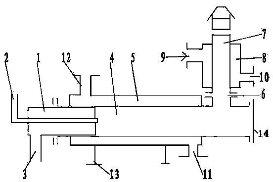
[0016] The device for burning and heating oil field casing associated gas of the present invention, such as figure 1 As shown, it includes a burner 1, a combustion chamber 4 and a flue 7. The burner is located at one end of the combustion chamber, the burner is provided with an air inlet 3 and a fuel inlet 2, and the combustion chamber is connected with the flue. The device is equipped with a high-temperature heat-absorbing chamber 5 and a low-temperature heat-absorbing chamber 8. The high-temperature heat-absorbing chamber 5 is arranged coaxially with the combustion chamber. The high-temperature heat-absorbing medium inlet 11 is located on the side where the high-temperature 12 is located at the side of the high-temperature combustion chamber close to the burner. The low-temperature heat-absorbing chamber 8 is arranged coaxially with the flue, the low-temperature heat-absorbing medium inlet 9 is located on the side of the flue outlet, and the low-temperature heat-absorbing ...

Embodiment 2

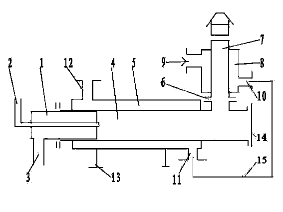
[0019] Another embodiment of the present invention is as figure 2 As shown, the low-temperature endothermic medium outlet 10 of the low-temperature endothermic chamber is connected to the high-temperature endothermic medium inlet 11 of the high-temperature endothermic chamber through a connecting pipeline 15, so that the high-temperature endothermic chamber 5 and the low-temperature endothermic chamber 8 are connected in series. Other structures are the same as in Embodiment 1.

[0020] Both the high-temperature heat-absorbing medium and the low-temperature heat-absorbing medium in this embodiment are crude oil. Crude oil at 40°C enters the low-temperature heat-absorbing chamber 7 through the low-temperature heat-absorbing medium inlet 9, and enters the high-temperature heat-absorbing chamber 5 through the low-temperature heat-absorbing medium outlet 9, the connecting pipeline 15, and the high-temperature heat-absorbing medium inlet 11 after being heated to 80±10°C. After be...


PUM


Abstract

The invention relates to a device for combusting and heating crude oil by using oilfield casing associated gas. The device comprises a combustor, a combustion chamber and a flue. The combustor is positioned at one end of the combustion chamber and is provided with an air inlet and a fuel inlet, and the combustion chamber is connected with the flue. The device is provided with a high-temperature heat absorption chamber and a low-temperature heat absorption chamber, the high-temperature heat absorption chamber and the combustion chamber are coaxially arranged, a high-temperature heat absorption medium inlet is positioned on one side of the flue, which is connected with the high-temperature combustion chamber, and a high-temperature heat absorption medium outlet is positioned on one side of the high-temperature combustion chamber, which is close to the combustor. The low-temperature heat absorption chamber and the flue are arranged coaxially, a low-temperature heat absorption medium inlet is positioned on one side of the flue, which is provided with an outlet, and a low-temperature heat absorption medium outlet is positioned on one side of the flue, which is connected with the combustion chamber. The device can be used for heating two heat absorption media respectively or heating the same heat absorption medium in a serial connection manner. The high-temperature heat absorption chamber is sleeved outside the combustion chamber, the low-temperature heat absorption chamber is sleeved outside the flue, heating media are heated in a flame separating manner, a heat transfer effect is good, and the heat utilization rate is high.

Description

Technical field: [0001] The invention belongs to the technical field of combustion and heating equipment, and relates to a device for burning and heating with oil field associated gas. Background technique: [0002] Most of the oilfield production adopts pipeline network gathering and transportation. During the production process of oil wells, along with the exploitation of formation crude oil, part of the associated gas in the oil reservoir also overflows into the annular space of tubing and casing to form casing associated gas. Although the oil well is equipped with a constant pressure release valve to automatically release the casing gas into the crude oil production pipeline, but in actual production operation, the back pressure of the oil well is high, so the casing gas cannot be released, and a large number of oilfield casings The associated gas must be vented on the spot, which not only wastes non-renewable resources, but also pollutes the atmospheric environment, a...

Claims


Application Information

Patent Timeline
Patent Type & Authority Patents(China)
IPC IPC(8): F24H1/00E21B43/25
Inventor 韩郁林段正利翟贵安李晨亮史威孟兵川
Owner SOBC ENERGY SOURCES SCI & TECH
Learn More