A kind of mining method of high viscosity oil

A mining method and viscous oil technology, which is applied in the fields of mining fluid, earthwork drilling, petroleum industry, etc. It can solve the problems of mining heavy oil reservoirs and high pour point oil reservoirs, difficulty in dehydration of production fluid, and high cost of water treatment. problems, to achieve the effect of improving oil displacement, enhancing oil recovery, and low equipment and operating costs

Active Publication Date: 2021-12-07
CHINA UNIV OF PETROLEUM (BEIJING)
View PDF10 Cites 0 Cited by
  • Summary
  • Abstract
  • Description
  • Claims
  • Application Information

AI Technical Summary

Problems solved by technology

Although the exploitation of heavy oil by steam injection can achieve significant recovery effects, there are still many problems: (1) Steam injection exploitation mainly uses high-temperature steam to heat the oil layer, which consumes a lot of energy, costs high and is harmful to the environment due to the production of a large amount of carbon dioxide and sewage. Adverse effects; (2) The water treatment cost of boiler water is high, and the dehydration treatment of produced fluid is difficult (the problem is particularly prominent when the water content is high and the liquid production rate is high); (3) Scaling is easy to occur due to the complex water quality of injected water and groundwater , mineral dissolution, and oil-water emulsification are also prone to occur; (4) complex production problems such as steam overburden and steam channeling are prone to occur; (5) high-viscosity heavy oil and high-condensation oil flow due to temperature drop during wellbore lifting In order to ensure the fluidity of heavy oil and high pour point oil in the wellbore, it is necessary to use methods such as downhole mixing of thin oil and wellbore electric heating
Therefore, for heavy oil reservoirs and high pour point oil reservoirs, the existing methods and processes are only auxiliary measures for high-temperature "water" steam injection, but cannot fundamentally solve the problems of high energy consumption and high cost of high-temperature "water" steam injection. core problem, and cannot replace steam injection to exploit heavy oil reservoirs and high pour point oil reservoirs

Method used


Image

  • A kind of mining method of high viscosity oil
  • A kind of mining method of high viscosity oil
  • A kind of mining method of high viscosity oil

Examples


Embodiment 11

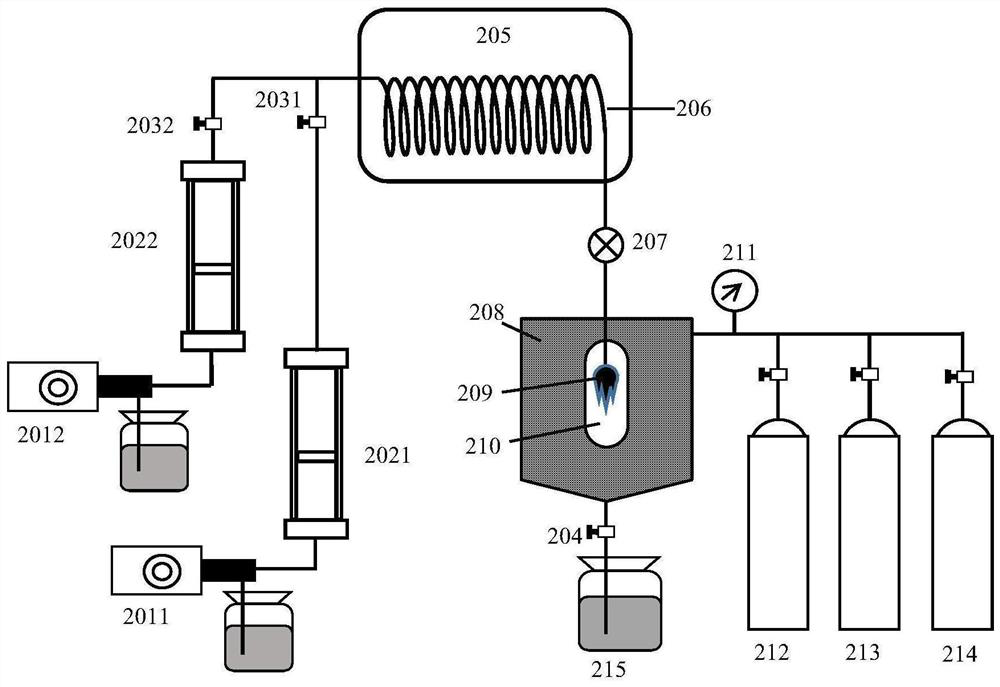
[0093] In this example, the low-viscosity oil is obtained by in-situ distillation and the safe injection temperature of the low-viscosity oil is determined by using the method of in-situ distillation of low-viscosity oil distillate huff and puff to exploit high-viscosity oil.

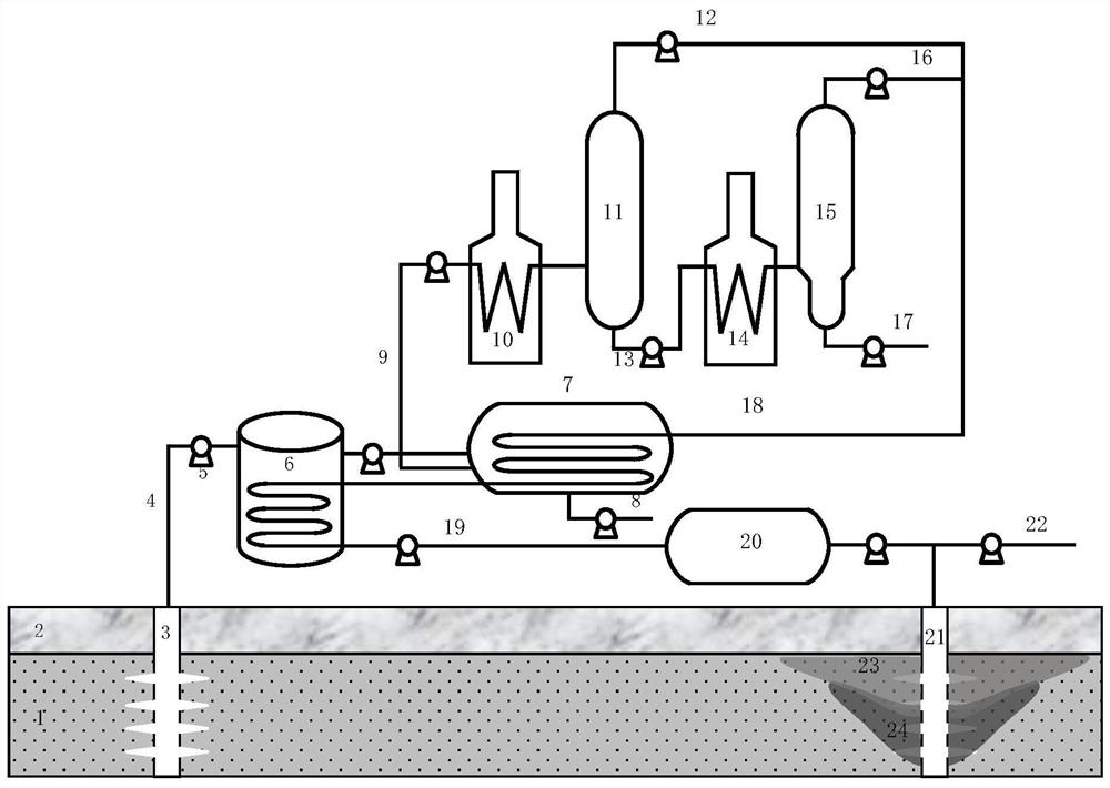
[0094] refer to figure 1 , the oil well 3 passes through the overlying rock layer 2 and enters the oil layer 1, and the high-viscosity oil produced by the oil well 3 is injected into the settling tank 6 through the high-viscosity oil pipeline 4 through the pump 5 to perform a dehydration and desanding treatment; after a dehydration and desanding process The treated high-viscosity oil is pumped into the dehydration and desalination treatment tank 7 for deep dehydration and desalination treatment, the high-viscosity oil is dehydrated to below 5%, and the brine produced by the dehydration and desalination treatment tank 7 is discharged through the brine pipeline; after dehydration and desalination treatment...

Embodiment 21

[0106] In this embodiment, the on-site distillation of low-viscosity oil fractions is used to develop thick-bed ultra-heavy oil reservoirs with horizontal wells deployed. In this example, an on-site distillation process similar to Example 1.1 was used to obtain injectable low-viscosity oil, and the light components and intermediate components obtained from the distillation were mixed to obtain viscosities of 150mPa·s, 75mPa·s and 37.5 at 50°C, respectively. mPa·s low viscosity oil.

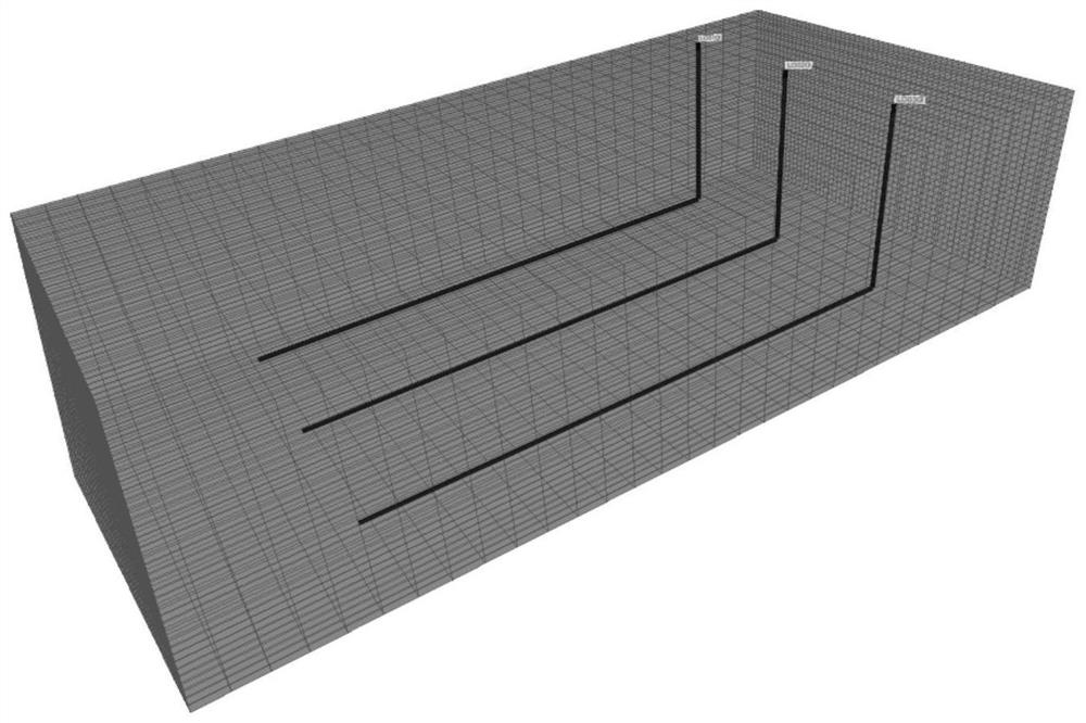
[0107] Such as image 3 As shown, a 600m×600m×30m horizontal, homogeneous and thick heavy oil reservoir has a top depth of 1000m and a thickness of 30m. Three horizontal wells are deployed in parallel. The length of each horizontal well is 400m. The position at the bottom of the oil layer is 3.5m, and the specific reservoir parameters are shown in Table 3. A homogeneous reservoir geological model with 60 × 30 × 30 grids was established. The size of the grid in the X direction is 5m, the size of ...

Embodiment 22

[0130] In this embodiment, thick-bed common heavy oil reservoirs with horizontal wells are exploited by using in-situ distillation of low-viscosity oil fraction huff and puff.

[0131] In this example, an in-situ distillation process similar to Example 1.1 was used to obtain injectable low-viscosity oil, and three viscosity grades of low-viscosity oil were obtained by mixing in different proportions. The viscosities at 50°C were 37.5 mPa·s, 75mPa·s and 100mPa·s.

[0132] The reservoir model produced is the same as in Example 2.1, except that the heavy oil is ordinary heavy oil, and the viscosity of the heavy oil is 1500mPa·s (the viscosity of degassed oil is 5260mPa·s) under formation conditions. Injection of high-temperature low-viscosity oil + nitrogen huff and puff production for 10 cycles, the injection-production cycle is 1 year, and a total of 10 years of production. In order to compare the effects, the injected low-viscosity oil temperatures were 50°C, 150°C, 180°C, an...


PUM

PropertyMeasurementUnit
radiusaaaaaaaaaa
radiusaaaaaaaaaa
viscosityaaaaaaaaaa

Abstract

The invention provides a method for recovering high-viscosity oil. The method is a method of injecting high-temperature low-viscosity oil or a combination of high-temperature low-viscosity oil and gas into high-viscosity oil reservoirs for huff and puff production; The high-viscosity oil is reduced in viscosity through dissolution and heating, and the formation pressure is increased; the high-temperature low-viscosity oil includes one or more combinations of light distillate and middle distillate obtained from in-situ distillation of high-viscosity oil; the The light distillate is obtained by atmospheric distillation of the dehydrated and desalted high-viscosity oil; the middle distillate is obtained by vacuum distillation of the heavy fraction obtained by dehydrating and desalting the high-viscosity oil subjected to atmospheric distillation.

Description

technical field [0001] The invention relates to a method for extracting high-viscosity oil, which belongs to the technical field of oil extraction. Background technique [0002] Viscous heavy oil and high pour point oil are generally exploited by thermal methods such as steam injection, among which steam injection exploitation methods include steam huff and puff, steam flooding and steam assisted gravity drainage. In addition to purifying the injected water and dehydrating the produced liquid during steam injection, a boiler is also required to heat the purified water to generate high-temperature steam. Although the exploitation of heavy oil by steam injection can achieve significant recovery effects, there are still many problems: (1) Steam injection exploitation mainly uses high-temperature steam to heat the oil layer, which consumes a lot of energy, costs high and is harmful to the environment due to the production of a large amount of carbon dioxide and sewage. Adverse ...

Claims


Application Information

Patent Timeline
Patent Type & Authority Patents(China)
IPC IPC(8): E21B43/16E21B43/22E21B43/24E21B43/40C10G7/00C10G7/06C10G53/02G01N25/26
CPCE21B43/16E21B43/166E21B43/24E21B43/40C10G7/06C10G7/00C10G53/02G01N25/26
Inventor 钟立国
Owner CHINA UNIV OF PETROLEUM (BEIJING)
Why Eureka
Try Eureka