Bond quality assessment method for new-old interface in building restoration
A technology for interface bonding and quality evaluation, which is applied in the directions of measuring devices, permeability/surface area analysis, suspension and porous material analysis, etc. It can solve the problem of loss of bonding ability, poor interface bonding quality, and difficult to accurately respond to repair The actual situation and other issues, to achieve the effect of high reference value
- Summary
- Abstract
- Description
- Claims
- Application Information
AI Technical Summary
Problems solved by technology
Method used
Image


Examples
Embodiment Construction
[0035] The process, principle and effect of the present invention will be further described in detail below in conjunction with specific implementation methods, drawings and specific experiments.
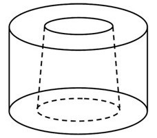
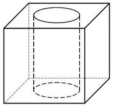
[0036] When the method is implemented, it includes the following steps: a. Take off the sample on the structure to be repaired (when testing the bonding performance between the repair material and the steel, the substrate is selected from steel), prepare the test piece matrix, and the test piece There is a hole in the shape of a truncated cone in the middle of the substrate, and the inclination angle of the cone surface is θ The range of change is 0°~30° (including 0° and 30°); b. Pour the repair material into the hole in the test piece matrix to form a truncated cone shape and complete the curing. There is room for at least one end of the hole during pouring. The thickness of the new pouring material is preferably 1 / 5 to 1 / 2 of the height of the hole; c. Use a microscope to observ...
PUM
 Abstract
Description
Claims
Application Information
 - Generate Ideas
- Intellectual Property
- Life Sciences
- Materials
- Tech Scout
- Unparalleled Data Quality
- Higher Quality Content
- 60% Fewer Hallucinations
Browse by: Latest US Patents, China's latest patents, Technical Efficacy Thesaurus, Application Domain, Technology Topic, Popular Technical Reports.
© 2025 PatSnap. All rights reserved.Legal|Privacy policy|Modern Slavery Act Transparency Statement|Sitemap|About US| Contact US: help@patsnap.com