
Test probe with ceramic coating and test instrument

A technology of test probes and test instruments, applied in the field of test probes, can solve problems such as low operating efficiency, inability to comply with the new IEC61010-31 standard at the same time, increase the complexity and cost of test probe structures, and achieve increased complexity and cost effect

Inactive Publication Date: 2012-09-19
MILWAUKEE ELECTRIC TOOL CORP
View PDF3 Cites 1 Cited by
  • Summary
  • Abstract
  • Description
  • Claims
  • Application Information

AI Technical Summary

Problems solved by technology

The problem that still exists for existing test probes is that they cannot simultaneously comply with the new IEC61010-31 standard and be able to be plugged into an electrical socket
However, the reversible design of the test probe significantly increases the structural complexity and cost of the test probe
Users also need to configure test probes each time before measurement, resulting in low operational efficiency

Method used


Image

  • Test probe with ceramic coating and test instrument
  • Test probe with ceramic coating and test instrument

Examples


Embodiment Construction

[0017] In the appended claims and the foregoing description of the present invention, the word "comprises" or variants such as "includes" or "has" has an inclusive meaning, except when it is required by explicit language or must imply. The presence of the described features does not exclude the presence or addition of other features in various embodiments of the present invention.

[0018] As used herein and in the claims, "coupled" or "connected" refers to directly or indirectly electrically coupled or connected via one or more electronic devices unless otherwise specified.

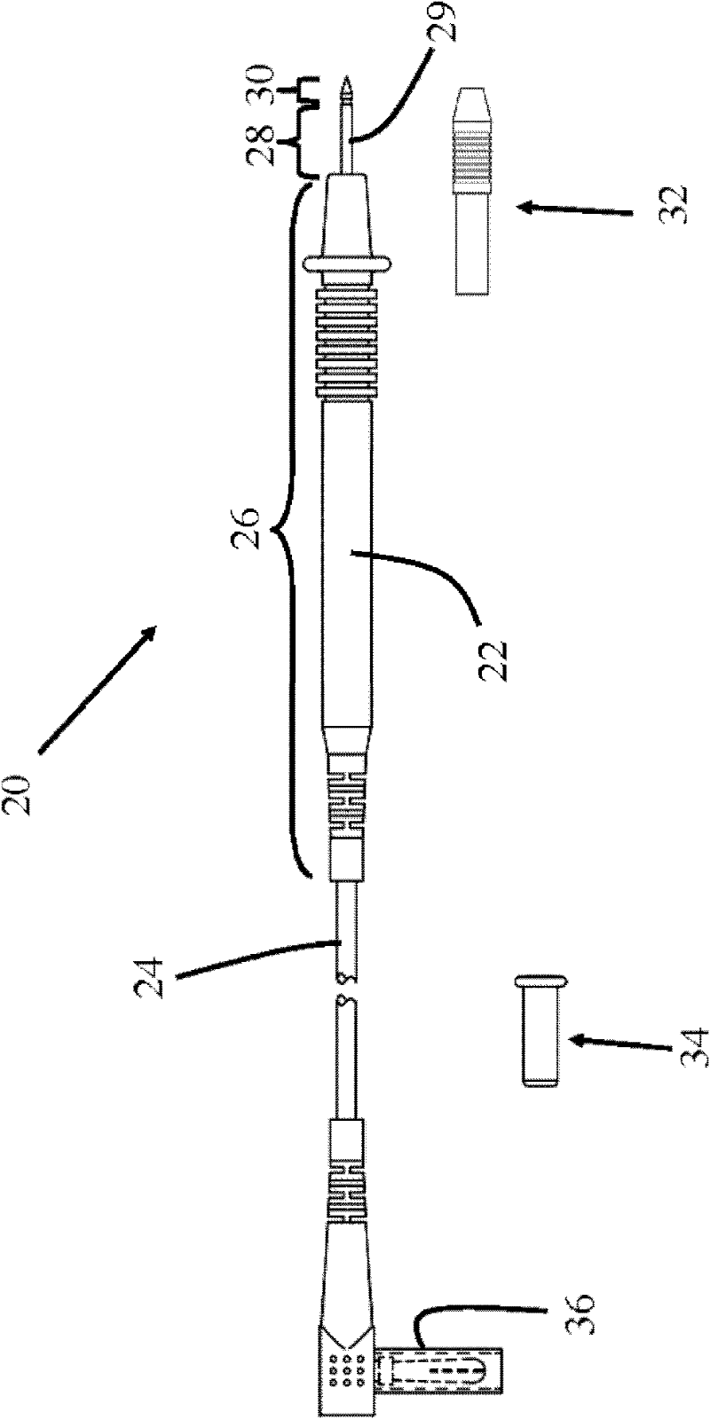
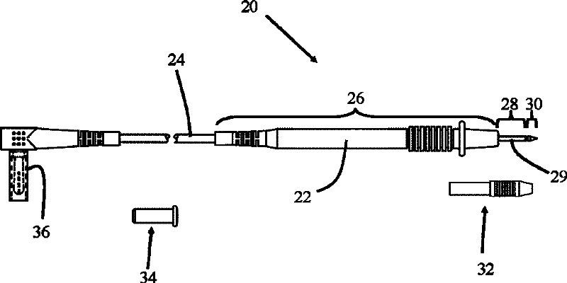
[0019] Reference now figure 1 , Connect a test probe 20 for measuring electrical parameters in various electronic devices to one end of the transmission line 24. The other end of the transmission line 24 is connected to the test instrument connector 36. The test instrument connector 36 is configured to fit in the socket or output terminal of the main body of the test instrument (not shown) so that the test...


PUM


Abstract

The invention discloses a test probe, comprising a conducting component with a first end which is limited by a conducting tip, and an insulating component surrounding a first part of the conducting component. The conducting component is covered with an insulating material layer at a second part between the first end and the first part. The test probe disclosed by the invention still meets the safety requirements of the IEC (International Electrotechnical Commission) standards without carrying different probe tips for being used for various test applications.

Description

Technical field [0001] The invention relates to a test probe on a test instrument, and more particularly to a test probe with insulation measures. Background technique [0002] Test instruments such as multimeters, voltmeters, oscilloscopes, etc. are used to measure electrical parameters in various electrical equipment. A typical test instrument uses multiple test probes connected to input / output terminals located on the main body of the test instrument to measure various electrical parameters. The test probe usually has a test end with a conductive tip to contact the object to be measured. [0003] Generally, different test tip tips are used for various test applications. Under the guidance of the Technical Committee (TC66), the International Electrotechnical Committee (IEC) formed a safety standard for test and measuring instruments involving test probes, which became IEC61010-031. The standard specifies the requirements for test probe tips for various test applications. For ...

Claims


Application Information

Patent Timeline
Patent Type & Authority Applications(China)
IPC IPC(8): G01R1/067
CPCG01R1/06788
Inventor 王茂川杨道军谢籼原
Owner MILWAUKEE ELECTRIC TOOL CORP
Learn More