Color image forming apparatus

A color image, intermediate transfer unit technology, applied in the direction of electric recording process applying charge pattern, equipment for applying electric recording process of charge pattern, electric recording technique, etc. become a hindrance, etc.

Inactive Publication Date: 2012-09-19
KONICA MINOLTA BUSINESS TECH INC
View PDF12 Cites 1 Cited by
  • Summary
  • Abstract
  • Description
  • Claims
  • Application Information

AI Technical Summary

Problems solved by technology

However, the provision of interference prevention protrusions on the main body of the device affects the external design, and the provision of interference prevention protrusions on the side of the intermediate transfer unit may cause problems when the intermediate transfer belt is transferred from the intermediate transfer unit to the intermediate transfer unit. Problems that will become an obstacle when the printing unit is removed
In addition, although a method of providing a stopper at the rotation fulcrum of the intermediate transfer unit is also considered, the stopper is likely to receive excessive stress due to the rotational moment, and there is a possibility that the stopper may be damaged.

Method used


Image

  • Color image forming apparatus
  • Color image forming apparatus
  • Color image forming apparatus

Examples


Embodiment 1

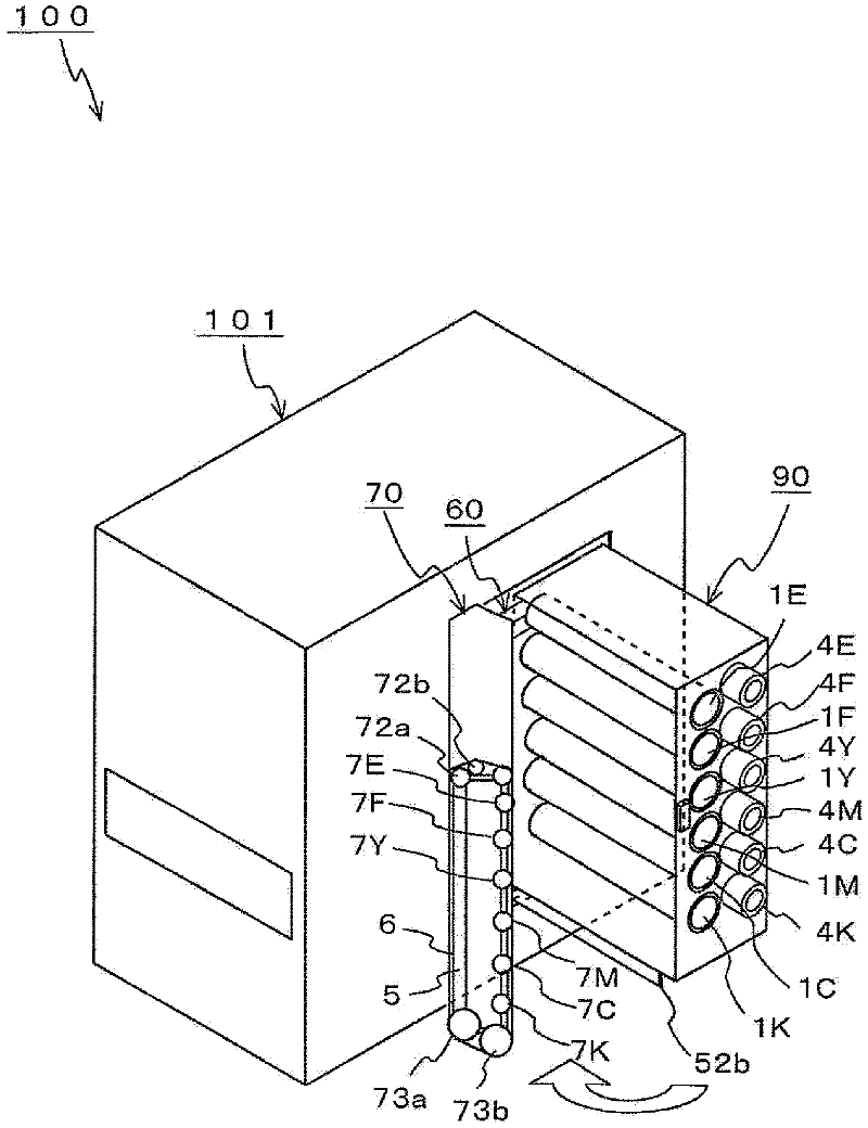
[0119] refer to figure 2 , an example of opening and closing of the intermediate transfer unit 70 according to the first embodiment will be described. In this embodiment, the intermediate transfer unit 70 has a structure that can be inserted into and removed from the apparatus main body 101 together with the processing rack unit 90 , and can be vertically positioned relative to the processing rack unit 90 in a door-like manner. Opening and closing.

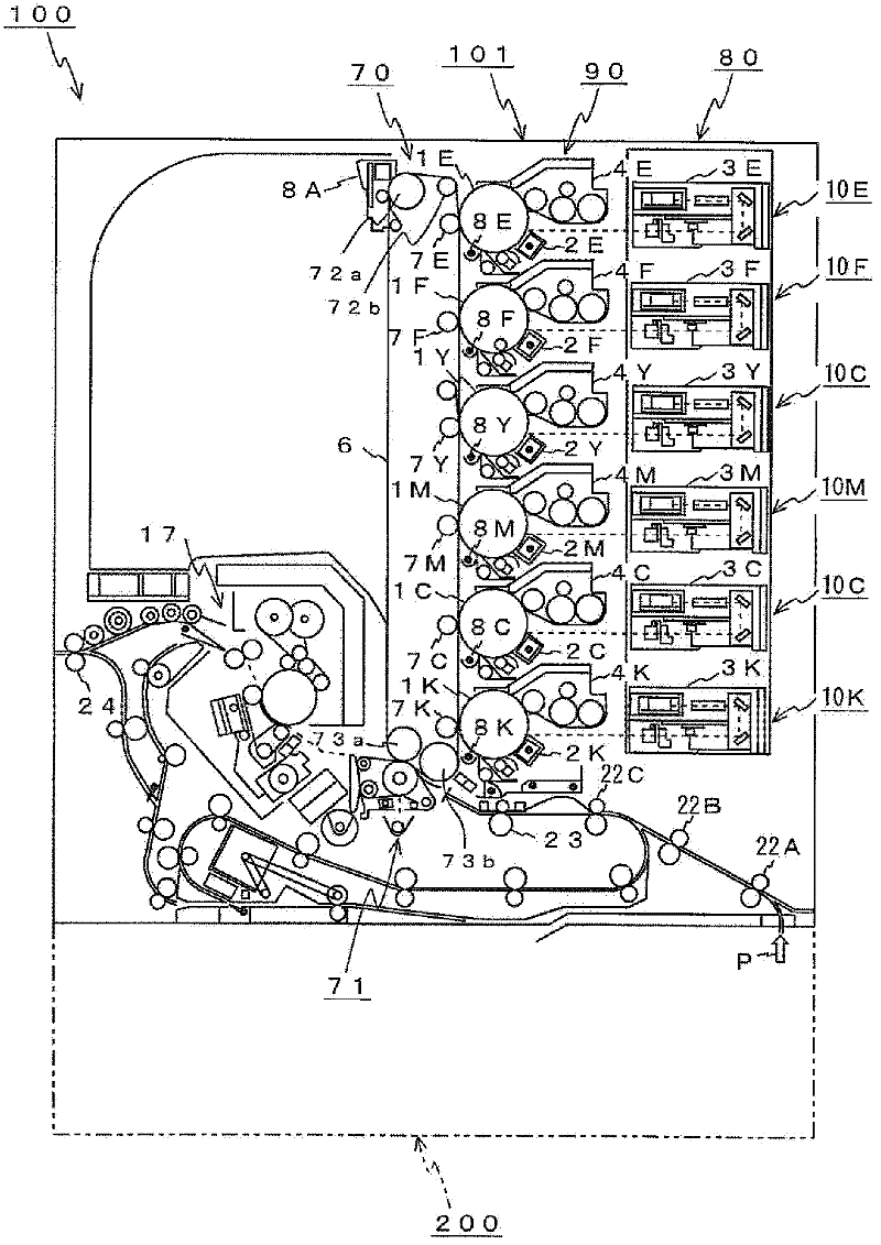
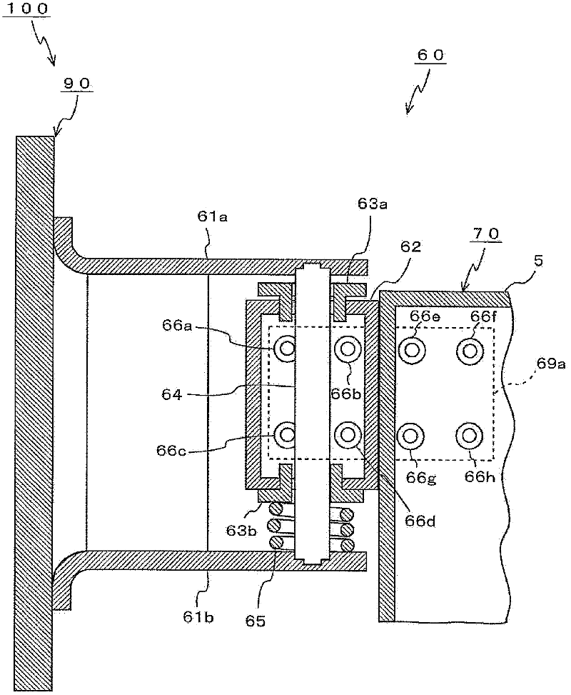
[0120] figure 2 The illustrated intermediate transfer unit 70 is adjacent to the processing rack unit 90 , and is disposed near the approximate center of the apparatus main body 101 when viewed from the front side. The intermediate transfer unit 70 is mounted so as to be freely openable and closable in a vertical door shape via a rotary hinge portion 60 provided on the rear side (rear side) of the process rack unit 90 . The rotary hinge portion 60 constitutes a fulcrum of rotation between the intermediate transfer unit 70 and...

Embodiment 2

[0156] Next, refer to Figure 10-12 The temporary fixing mechanism 20 in the color printer 100 according to the second embodiment will be described. for Figure 10 In the color printer 100 shown, the intermediate transfer unit 70 has a structure that can be inserted and removed from the device main body 101 together with the processing stand unit 90, and can be opened and closed in a vertical state in the form of a door. A temporary fixing mechanism 20 is provided between the bracket unit 90 and the intermediate transfer unit 70 .

[0157] The temporary fixing mechanism 20 is arranged, for example, near the approximate center of the composite unit 201 in a state where the intermediate transfer unit 70 is closed with respect to the process rack unit 90 . In this example, in the state where the intermediate transfer unit 70 is closed relative to the processing rack unit 90, the temporary fixing mechanism 20 is disposed on the boundary line formed between one end of the transfe...

Embodiment 3

[0170] Next, refer to Figures 13 to 17 , the stopper connecting mechanism 30 in the color printer 100 according to the third embodiment will be described. In this example, when the intermediate transfer unit 70 described in the first to second embodiments is opened, the pressing member 31 is rotated by applying the rotational force of the rotary hinge portion 603, whereby the pressing member 31 is moved from the device The position where the main body portion 101 interferes and the position where the intermediate transfer belt 6 is included protrudes.

[0171] Figure 13 The color printer 100 shown in A includes, in addition to the intermediate transfer unit 70 described in the first to second embodiments, a pressing member 31 and a stopper connection mechanism 30 constituting an example of a first connection mechanism. The stopper connection mechanism 30 has rotation transmission gears 32, 34, gear fixing pins 33, 35, arm support bearings 36, 38, and an arm support shaft 3...


PUM


Abstract

The invention relates to a color image forming apparatus capable of ensuring easy replacement of an intermediate transfer belt and others, using an improved method for pulling out an intermediate transfer unit, despite a possible increase in the unit size. The color image forming apparatus includes: a main body (101) of the apparatus that forms a color image; and an intermediate transfer unit (70) for transferring the color image formed by the main body of the apparatus, wherein the intermediate transfer unit (70) is configured to be removed from and to be inserted into the main body (101) of the apparatus, and wherein the intermediate transfer unit is configured to perform a door-like opening and closing movement. This structure allows the intermediate transfer unit (70) to be opened or closed like a door, with the intermediate transfer unit (70) removed from the main body (101) of the apparatus at the time of belt replacement, and permits the intermediate transfer belt (70) to be replaced, without having to dismount from the main body (101) of the apparatus the intermediate transfer unit (70) that may be difficult to remove due to an increase in the size of the color printer (100).

Description

technical field [0001] The present invention relates to a color image forming device suitable for a vertical tandem color printer, a color copier, a color multifunction machine, etc. having a large intermediate transfer unit and forming a color image. Background technique [0002] In recent years, color printers that form color images based on color image information, and color copiers and multifunction machines that have a scanning function that reads an image of a document and outputs an image signal for color image reproduction are increasingly used. For example, digital color printers that form color images based on red (R), green (G) and blue (B) image data from an external device such as a personal computer are widely used. [0003] Among such printers, according to an electrophotographic color printer, the color printer includes an image forming unit based on yellow (Y) and magenta (M) colors obtained by color-converting RGB image data. Color toner images are formed ...

Claims


Application Information

Patent Timeline
Patent Type & Authority Applications(China)
IPC IPC(8): G03G15/01G03G15/16G03G21/16
CPCG03G21/1623G03G2221/1642G03G21/168
Inventor 富野俊彰川元基史今野忍
Owner KONICA MINOLTA BUSINESS TECH INC
Why Eureka
Try Eureka