Scanning drive method for smectic phase liquid crystal display

A liquid crystal display and scanning driving technology, applied in the field of scanning driving, can solve the problems of cost, high voltage amplitude, and aggravation of the cumulative effect of swiping, so as to reduce the cumulative effect of swiping, achieve DC balance, and ensure normal display. Effect

Inactive Publication Date: 2013-10-02
HALATION PHOTONICS CORP
View PDF6 Cites 0 Cited by
  • Summary
  • Abstract
  • Description
  • Claims
  • Application Information

AI Technical Summary

Problems solved by technology

[0004] However, since the values ​​of the voltage waveforms on the row and column electrodes of the current smectic liquid crystal display are fixed, that is, they are all high-frequency high-voltage positive and negative pulses with a voltage amplitude of Umx, therefore, the voltage amplitude Umx must be set to be The voltage energy required to drive the highest energy state (i.e. fully transparent state)
[0005] It can be seen that the current high-frequency high-voltage positive and negative pulses used by smectic liquid crystal display screens have caused the problems of overall high voltage amplitude and waste of voltage energy, and the overall high voltage amplitude will also lead to the cumulative effect of screen brushing. aggravate
[0006] In addition, the current high-frequency high-voltage positive and negative pulses used on the row and column electrodes of the smectic liquid crystal display are powered by positive and negative power supplies, which require two sets of high-voltage isolation devices to realize, the waveform is complex to realize, the drive is difficult, and the cost is high.

Method used


Image

  • Scanning drive method for smectic phase liquid crystal display
  • Scanning drive method for smectic phase liquid crystal display
  • Scanning drive method for smectic phase liquid crystal display

Examples


Embodiment Construction

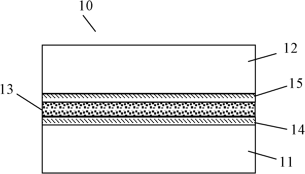
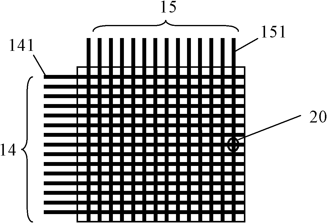
[0037] The scanning driving method of the present invention is a method used on a smectic liquid crystal display. Such as figure 2 with image 3 As shown, the smectic liquid crystal display screen 10 includes a first base layer 11 and a second base layer 12, and the material of the first base layer 11 and the second base layer 12 can be transparent glass or plastic. Between the first base layer 11 and the second base layer 12, there is a mixed layer 13 formed by mixing smectic liquid crystals and additives. The smectic liquid crystals (also known as smectic liquid crystals, which appear as smectic liquid crystal molecules microscopically, see below) are compounds with siloxy groups, tetracyanotetraoctylbiphenyl or tetradecyl tetraacetate Any one or any mixture of cyanobiphenyls. The additives are compounds with conductive properties, such as hexadecyltriethylammonium bromide and other compounds containing conductive ions. A first conductive electrode layer 14 is plated on...


PUM


Abstract

The invention discloses a scanning drive method for a smectic phase liquid crystal display, to perform scanning drive for all lines. The scanning drive for each line comprises the following steps: applying 0V voltage to all lines and columns in a waiting period; in a scanning period, applying a line scanning period pulse on a line to be subjected to scanning drive, and applying 0V voltage to other lines not to be subjected to scanning drive, applying full-transparent state column scanning period pulse to a column corresponding to pixel points which are on the line to be subjected to scanning drive and need to be driven into a full-transparent state, and applying fog light shielding state column scanning period pulse to a column corresponding to pixel points which are on the line to be subjected to scanning drive and need to maintain a fog light shielding state; and in a DC balance period, applying positive voltage with amplitude value being Um to other lines not to be subjected to scanning drive and applying 0V voltage to the line to be subjected to scanning drive and all columns. According to the invention, the voltage waveform can be achieved simply, the problem that the drive voltage of a column electrode is slightly higher is solved, the influence of screen refreshing accumulative effect is reduced, the drive cost and the complexity are lowered, and the DC balance and normal image display are guaranteed.

Description

technical field [0001] The invention relates to a scanning driving method, in particular to a scanning driving method applied to a smectic liquid crystal display. Background technique [0002] At present, smectic liquid crystal displays (also called smectic liquid crystal displays) generally use high-frequency high-voltage positive and negative pulses as voltage waveforms for driving row and column electrodes. For example, the high-frequency high-voltage positive and negative pulses can be composed of figure 1 The waveform form realized by the positive and negative pulse pairs composed of the positive pulse and the negative pulse is shown. The positive and negative pulses in the high-frequency high-voltage positive and negative pulses are symmetrical to each other, and the voltage amplitudes are equal, both of which are Umx. [0003] In actual implementation, it can be found that since the smectic liquid crystal display has a threshold voltage, therefore, in order to drive...

Claims


Application Information

Patent Timeline
Patent Type & Authority Patents(China)
IPC IPC(8): G09G3/36
Inventor 任宇夏兴隆孙刚
Owner HALATION PHOTONICS CORP
Why Eureka
Try Eureka