
A High Efficiency FM Transmitter, Power Amplifier Circuit Structure and Design Method

A technology for power amplifiers and FM transmitters, applied in power amplifiers, electrical components, transmission systems, etc., can solve the problems of inability to achieve harmonic control conditions, work efficiency affecting the power consumption of the whole machine, and reducing power amplifier efficiency performance, etc. The design is simple and easy to implement, conducive to integration and miniaturization, and the effect of reducing heat dissipation requirements

Inactive Publication Date: 2017-04-19
INST OF ELECTRONICS ENG CHINA ACAD OF ENG PHYSICS
View PDF7 Cites 0 Cited by
  • Summary
  • Abstract
  • Description
  • Claims
  • Application Information

AI Technical Summary

Problems solved by technology

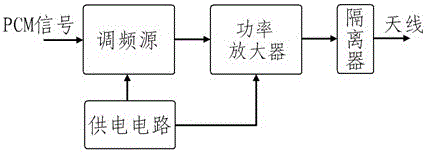
[0007] But the above-mentioned prior art still has the following disadvantages: the power amplifier is the main energy-consuming component in the transmitter, and its working efficiency directly affects the power consumption of the whole machine
[0013] The drain voltage of class E power amplifier is high (the drain current of reverse class E power amplifier is high), which reduces the safety of the device when it works; class F power amplifier has complex harmonic control circuit, and the actual circuit design cannot realize the ideal Harmonic control conditions, reducing the efficiency performance of the power amplifier
[0014] At present, the design technology of Class E and F power amplifiers still belongs to the scope of academic research, and there are few domestic engineering application reports

Method used


Image

  • A High Efficiency FM Transmitter, Power Amplifier Circuit Structure and Design Method
  • A High Efficiency FM Transmitter, Power Amplifier Circuit Structure and Design Method
  • A High Efficiency FM Transmitter, Power Amplifier Circuit Structure and Design Method

Examples


Embodiment 1

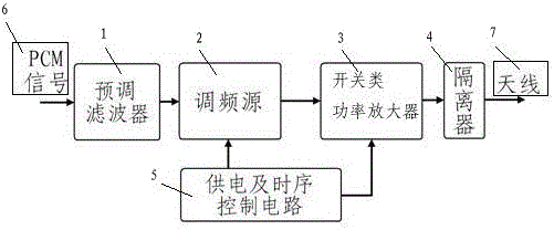
[0041] As a preferred embodiment of the present invention, it includes a frequency modulation source 2, a power amplifier, an isolator 4, a power supply circuit and an antenna 7, and also includes a pre-tuning filter 1 for filtering the input PCM signal 6, the preset The tuning filter 1 is connected to the frequency modulation source 2, the power amplifier is a switching power amplifier 3, and the switching power amplifier 3 selects a GaAs or GaN device, and the gate voltage of the GaAs or GaN device is negatively biased, and the power supply circuit It is a power supply and timing control circuit 5, and GaAs or GaN devices cooperate with the power supply timing.

Embodiment approach

[0043] As the best implementation mode of the present invention is as follows:

[0044] The high-efficiency FM transmitter provided by the present invention includes the following parts:

[0045] The pre-tuning filter 1 filters the input PCM signal 6 to filter out its high-frequency components and retain the fundamental frequency components, thereby reducing the useful signal bandwidth. The pre-tuning filter 1 can be realized by a fifth-order Bessel low-pass filter structure.

[0046] The frequency modulation source 2 generates the frequency modulation signal required by the system. The PCM signal 6 is sent to the frequency modulation source 2 after being pre-modulated and filtered to perform frequency modulation on the carrier signal. The unit can adopt a phase-locked frequency modulation structure, which is the same as the existing frequency modulation transmitter scheme, so it is not necessary to repeat it here.

[0047] The high-efficiency power amplifier amplifies the ...

Embodiment 3

[0058] Example 3 - Verification of the feasibility of the inventive solution

[0059] In order to verify the feasibility of the proposed scheme, the present invention has carried out simulation design verification, and developed a prototype. Some measured data are given here.

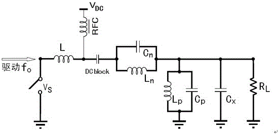
[0060] Based on the above power amplifier structure and design method, the present invention designs an S-band high-efficiency power amplifier by using GaN devices. When the power supply is 27V, the DC current is 0.5345A, the output power is 40.3dBm, the gain is 13.3dB, the working efficiency is 78.1%, and the power added efficiency is 75.2%.

[0061] When the operating frequency, input signal power and gate supply voltage are constant, the drain voltage is scanned from small to large, and the output power and DC current of the power amplifier are tested and its gain, work efficiency and power added efficiency (PAE) are calculated. , so that the relationship curve between power amplifier performance a...


PUM


Abstract

The invention discloses a high-efficiency frequency modulation transmitter, which relates to a transmitting device in the wireless monitoring and control communication technology and comprises a frequency modulation source, a power amplifier, an isolator, a power supply circuit, an antenna and a premodulation filter, wherein the premodulation filter is used for filter processing on PCM (Pulse Code Modulation) signals that are input; the premodulation filter is connected with the frequency modulation source; the power amplifier is a switching power amplifier; the switching power amplifier selects a GaAs device or a GaN device; the grid voltage of the GaAs device or the GaN device is negative electricity offset; the power supply circuit is a power supply and time-sequence control circuit; and the GaAs device or the GaN device is matched with power supply time-sequence. The high-efficiency frequency modulation transmitter reduces power consumption of the transmitter, reduces the heat dissipation requirement of the transmitter, and facilitates the integration and the miniaturization of the transmitter.

Description

technical field [0001] The invention relates to a transmitting device of wireless measurement and control communication technology, in particular to a frequency modulation transmitter based on a high-efficiency switching power amplifier. Background technique [0002] One, technical background relevant to the present invention [0003] The FM transmitter is an important component of the aviation measurement and control system. In recent decades, it has the following development trends: high code rate, digital programmable, miniaturization, etc. Among them, miniaturization is a comprehensive manifestation of various technologies, and it is also the key to narrowing the performance gap between my country's measurement and control equipment and similar equipment in developed countries. There is an important restrictive factor to realize the miniaturization of FM transmitter—the efficiency of converting DC energy into microwave energy. For medium and long-distance measurement ...

Claims


Application Information

Patent Timeline
Patent Type & Authority Patents(China)
IPC IPC(8): H04B1/04H03F3/20
Inventor 曹韬吕立明
Owner INST OF ELECTRONICS ENG CHINA ACAD OF ENG PHYSICS
Learn More