Supercharge Your Innovation With Domain-Expert AI Agents!

a signal transmission system

A signal transmission and optical signal technology, applied in the field of communications, can solve the problems of cluttered lines and high costs, and achieve the effects of convenient operation, reduced impact, and low wiring costs

Inactive Publication Date: 2015-09-23
SHENZHEN COSHIP ELECTRONICS CO LTD
View PDF8 Cites 0 Cited by
  • Summary
  • Abstract
  • Description
  • Claims
  • Application Information

AI Technical Summary

Problems solved by technology

Using parallel wiring, it is necessary to connect multiple cable TV cables to the optical receiver at the same time, and the lines are messy, especially when additional users need to be added to the existing network, long-distance wiring needs to be costly

Method used


Image

  • a signal transmission system
  • a signal transmission system
  • a signal transmission system

Examples


Embodiment Construction

[0029] The following will clearly and completely describe the technical solutions in the embodiments of the present invention with reference to the accompanying drawings in the embodiments of the present invention. Obviously, the described embodiments are only some, not all, embodiments of the present invention. Based on the embodiments of the present invention, all other embodiments obtained by persons of ordinary skill in the art without creative efforts fall within the protection scope of the present invention.

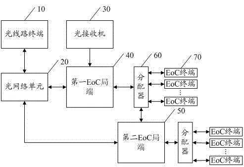
[0030] refer to figure 2 , is a schematic composition diagram of the first embodiment of the signal transmission system of the present invention. The signal transmission system includes: an optical line terminal 10 , an optical network unit 20 , an optical receiver 30 , a first EoC central office 40 , a second EoC central office 50 , a distributor 60 and an EoC terminal 70 .

[0031] The input end of the first EoC central office 40 is used to be electrically conn...


PUM


Abstract

The embodiment of the invention discloses a system for signal transmission, which comprises a first EoC (Ethernet over coax) local side, a distributor, a second EoC local side and an EoC terminal; an input end of the first EoC local side is used for being electrically connected with a photoreceiver which is used for receiving television photosignals and converting the television photosignals to television radio frequency photosignals; an input end of the distributor is electrically connected with an output end of the first EoC local side; an input end of the second EoC local side is electrically connected with an output end of the distributor; and the EoC terminal is electrically connected with the output end of the first EoC local side or an output end of the second EoC local side. According to the invention, line distribution can be completed simply with low cost, so as to provide convenience for a user to use.

Description

technical field [0001] The present invention relates to the communication field, in particular to a signal transmission system. Background technique [0002] Ethernet over COAX (EoC), which is a transmission technology of Ethernet signals on coaxial cables, is now widely used. In residential quarters, users not only need to watch cable TV, but also need to surf the Internet, download or upload data. In the past, after the optical receiver received the cable TV signal, it was transmitted to the user through the cable TV cable, and the Ethernet signal was sent to the optical network unit (Optical Network Unit, ONU) in the form of broadcast through the optical line terminal (Optical Line Terminal, OLT). ), and then transmitted to the user by the ONU through the network cable, which requires double wiring, which is costly and troublesome. The coaxial cable transmission of cable TV signal and Ethernet signal can save wiring cost, facilitate the use of users, and help the realiz...

Claims


Application Information

Patent Timeline
IPC IPC(8): H04B10/27H04N7/10H04N21/61H04B10/60
Inventor 徐付强
Owner SHENZHEN COSHIP ELECTRONICS CO LTD
Features
  • R&D
  • Intellectual Property
  • Life Sciences
  • Materials
  • Tech Scout
  • Unparalleled Data Quality
  • Higher Quality Content
  • 60% Fewer Hallucinations
Learn More