Roller tappet

A technology of rollers and shells, which is applied in a field, can solve the problem of high cost of roller tappets and achieve the effect of reducing weight

Inactive Publication Date: 2012-09-19
SCHAEFFLER TECH AG & CO KG
View PDF6 Cites 20 Cited by
  • Summary
  • Abstract
  • Description
  • Claims
  • Application Information

AI Technical Summary

Problems solved by technology

[0003] The aforementioned roller tappet has the disadvantage that it

Method used


Image

  • Roller tappet
  • Roller tappet
  • Roller tappet

Examples


Embodiment Construction

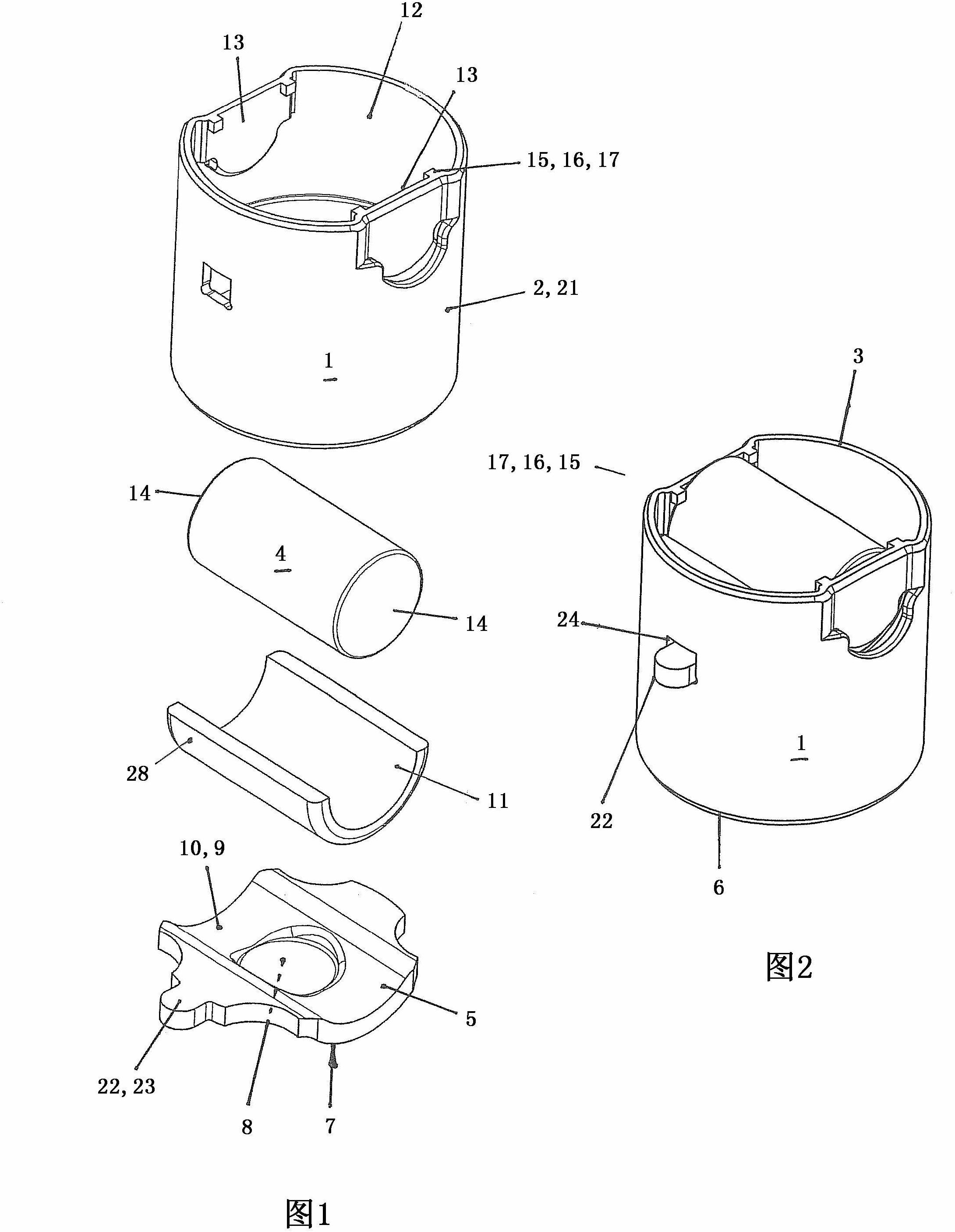
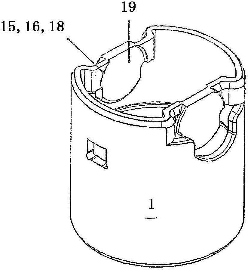
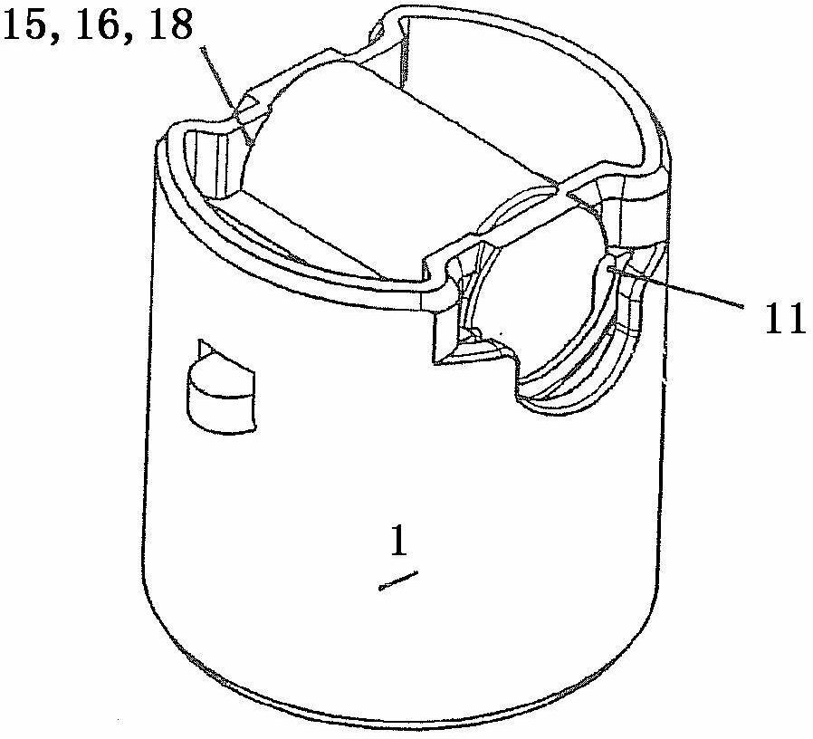
[0028] figure 1 A roller tappet 1 is disclosed, as in the case of its use as counter slide / counterpart for cams or eccentrics in high-pressure fuel pumps, for example for delivering diesel fuel. The roller tappet 1 has an approximately cylindrical housing 2 , via an outer wall 21 of which is guided in a recess of a high-pressure fuel pump or in a surrounding structure. In the region of the drive-side end 3 , the rollers 4 pass transversely through the housing 2 . According to Figure 1 to Figure 6 As a solution, the rollers 4 rest with their end faces 14 against the inner surface of the respective flat part 13 . The flat plate 13 is configured as a material depression.

[0029] The rollers 4 are slidably supported in a shell 11 which is separated from the roller rings as standard components. For example, splitting is conceivable as a separation process, so that each raceway can form two or three shell parts.

[0030] The shell part 11 is accommodated in a complementary mo...


PUM


Abstract

The invention relates to a roller tappet (1) for a high pressure fuel pump, having a housing (2) in which a friction bearing mounted roll (4) serving as a run-up of a cam is immanent in the drive-side face (3) thereof, wherein the housing (2) has a bridge piece (5) underneath the roll (4) when viewed in the direction of the housing which has an attachment (8) for a tappet follower part on the one end face (7) thereof facing a drive-side face (6) of the housing (2) and wherein a shell part (11) separate from a rolling ring, such as a half or third-shell, sits in a cylindrical molding (9) of another drive-side end face (10) of the bridge part (5), in which the friction bearing mounted roll (4) runs directly.

Description

technical field [0001] The invention relates to a roller tappet, in particular for a high-pressure fuel pump or a valve train of a mass-regulated or quantity-regulated internal combustion engine, the roller tappet having a housing, The housing itself has inherently slidingly mounted rollers at its drive-side end for abutment / activation of cams or eccentrics, wherein, viewed in the direction of the housing, the housing is positioned between the rollers There is a bridge underneath, which has a contact for the tappet driver on its end face facing the driven-side end of the housing. Background technique [0002] A roller tappet of this type is known from DE 3247026A1. The rollers sit in cylindrical recesses on the drive side of the housing. The housing, with its drive-side end, is higher than half the height of the roller in order to support the roller, which is accommodated in a web connected in one piece to the housing. The axial fixation of the roller is provided by a sep...

Claims


Application Information

Patent Timeline
IPC IPC(8): F01L1/14F02M59/10F04B1/04
CPCF04B1/0408F01L2105/00F01L2107/00F01L1/146F04B1/0417F02M59/102F04B9/042F04B9/045F04B1/0426F01L2305/00F01L2307/00F01L1/14F02M59/10F04B1/04
Inventor 斯特凡·多恩诺伯特·盖耶卡斯藤·库赫特
Owner SCHAEFFLER TECH AG & CO KG
Why Eureka
Try Eureka