

Washing unit
A technology for cleaning devices and cleaning tanks, applied in cleaning methods and utensils, cleaning methods using liquids, chemical instruments and methods, etc., can solve the problems of relatively large energy consumption and complex piping systems of cleaning devices, and achieve energy saving, The effect of simplifying the piping structure
- Summary
- Abstract
- Description
- Claims
- Application Information
AI Technical Summary
Problems solved by technology
Method used
Image


Examples
Embodiment Construction
[0011] The present invention will be further described below in conjunction with accompanying drawing.
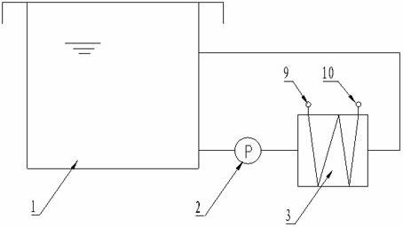
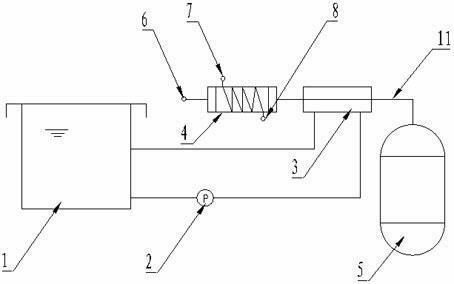
[0012] A cleaning device, comprising a cleaning tank 1 connected to each other through pipelines, a circulation pump 2, a heat exchanger 3, a steam generator 5, and a condenser 4, the steam generator 5 and the condenser 4 are connected through a connecting pipe 11, The connecting pipe 11 passes through the body of the heat exchanger 3 .
[0013] A cold water pipeline is arranged in the condenser 4 .
[0014] The hydrocarbon solvent vapor generated by the steam generator 5 has a temperature of about 110°C. The steam generator 5 and the condenser 4 are connected through a connecting pipe 11. After the hydrocarbon solvent vapor generated by the steam generator 5 passes through the condenser 4, because the A cold water pipeline is provided with a cold water inlet 7 and a cold water outlet 8. After the cold water pipeline is fed with cold water, the hydrocarbon solvent vapor be...
PUM
 Abstract
Description
Claims
Application Information