Air conditioner for vehicles

a technology for air conditioners and vehicles, applied in vehicle components, vehicle heating/cooling devices, transportation and packaging, etc., can solve the problems of increasing the thickness in the “t” direction, the size of the air conditioner for the vehicle, and the thickness in the back-and-forth direction, so as to reduce the packaging, reduce manufacturing costs, and simple piping structure

Active Publication Date: 2018-11-01
HANON SYST
View PDF2 Cites 3 Cited by
  • Summary
  • Abstract
  • Description
  • Claims
  • Application Information

AI Technical Summary

Benefits of technology

[0011]Accordingly, the present invention has been made to solve the above-mentioned problems occurring in the prior arts, and it is an object of the present invention to provide an air conditioner for a vehicle with a heat pump system structure, which hats a simple piping structure and enhances heating performance, thereby reducing a package, and making common use with an air conditioner for an internal combustion engine possible.
[0022]According to the present invention, the air conditioner for a vehicle can reduce manufacturing costs because it can reduce a package and make common use with an air conditioner for an internal combustion engine possible by having the simple piping structure and enhancing heating performance. Moreover, the air conditioner for a vehicle can reduce total weight, volume and expense because it does not require a defrosting line (pipe) and a dehumidification line (pipe) and can reduce the number of valves. Additionally, the air conditioner for the vehicle can reduce risk factors in safety of passengers caused by high voltage parts because it does not require an internal high voltage PTC heater.

Problems solved by technology

The conventional air conditioner for the vehicle has a disadvantage in that its size increases in the back-and-forth direction of the vehicle (“T” direction in FIG. 1) because the high pressure heat exchanger 62, which is an internal condenser, and the high voltage PTC heater 70 are mounted inside the air-conditioning case 10.
If the high voltage PTC heater is used, the thickness in the “T” direction becomes increased more, so improvement of heating performance and reduction of the size cannot be achieved at the same time.
Additionally, the conventional air conditioner for the vehicle cannot be in common use with an air conditioner for an internal combustion engine because the high pressure heat exchanger 62, which is an internal condenser, and the high voltage PTC heater 70 are used, and it increases the unit cost of production.
In addition, the conventional air conditioner for the vehicle has another disadvantage in that the entire piping arrangement becomes complicated because it requires a defrosting line and a dehumidification line for a defrosting mode and a dehumidification mode.

Method used


Image

  • Air conditioner for vehicles
  • Air conditioner for vehicles
  • Air conditioner for vehicles

Examples


Embodiment Construction

[0033]Hereinafter, reference will be now made in detail to exemplary embodiments of the present invention with reference to the attached drawings.

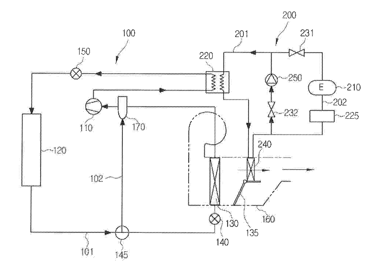
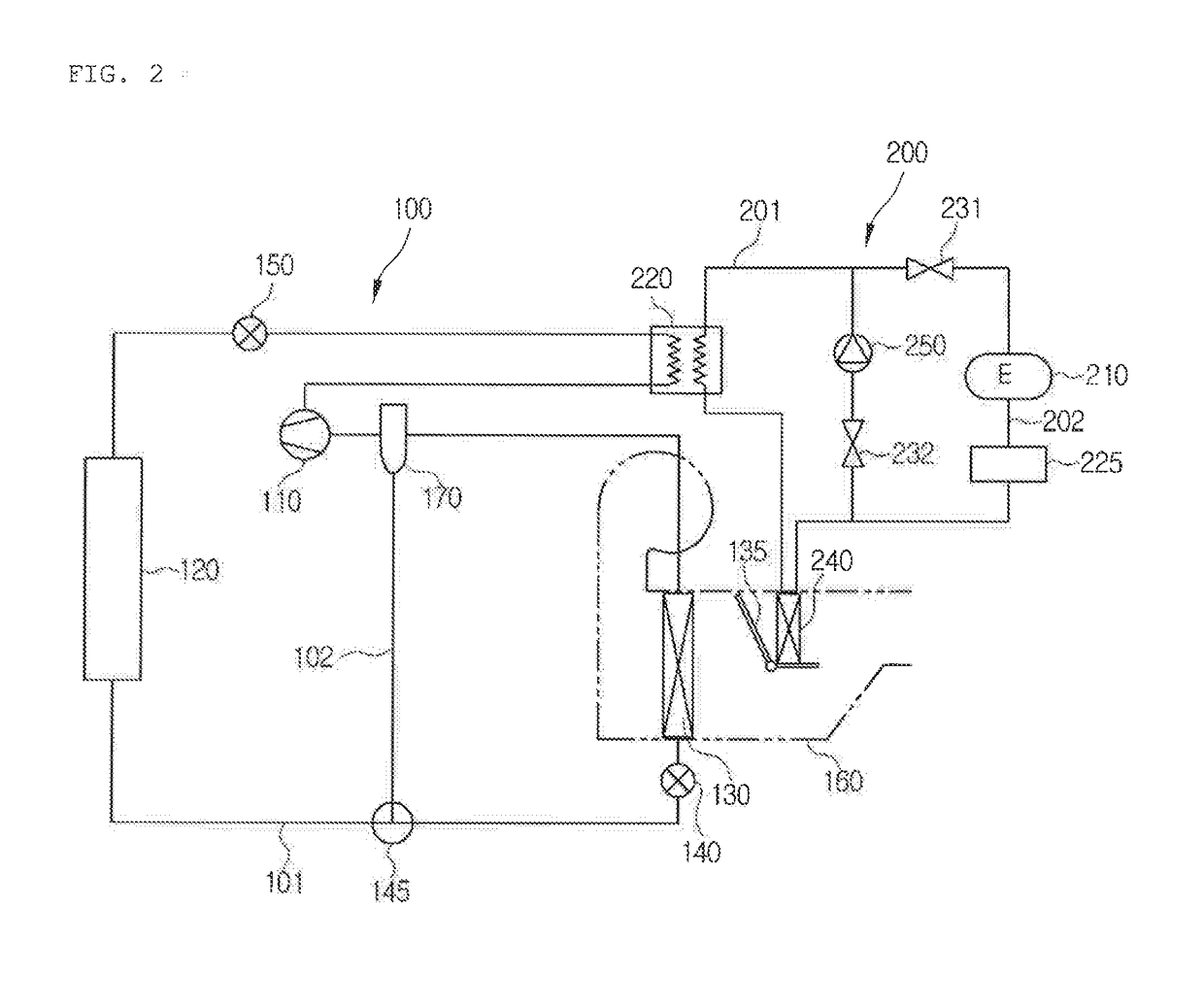
[0034]FIG. 2 is a view showing an air conditioner for a vehicle according to a first preferred embodiment of the present invention.

[0035]As shown in FIG. 2, the air conditioner for the vehicle according to the first preferred embodiment of the present invention includes a refrigerant circulation system 100 and a coolant loop 200. The refrigerant circulation system 100 circulates refrigerant and exchanges heat with air inside an air-conditioning case 160 in order to cool or heat the interior of the vehicle.

[0036]The coolant loop 200 includes a first heat exchanger, a second heat exchanger, a first coolant pipe 201, a second coolant pipe 202, and a first valve system.

[0037]The first heat exchanger exchanges heat with refrigerant of the refrigerant circulation system 100. The air conditioner for the vehicle raises temperature of coolant throu...


PUM


Abstract

The present invention relates to an air conditioner for a vehicle with a heat pump system structure, which has a simple piping structure and enhances heating performance, thereby reducing a package, and making common use with an air conditioner for an internal combustion engine possible.

Description

BACKGROUND OF THE INVENTIONField of the Invention[0001]The present invention relates to an air conditioner for a vehicle, and more particularly, to an air conditioner for a vehicle with a heat pump system structure, which can change a flow direction of refrigerant using one refrigerant cycle so as to selectively carry out cooling and heating.Background Art[0002]In general, an air conditioner for a vehicle includes a cooling system for cooling the interior of the vehicle and a heating system for heating the interior of the vehicle. The cooling system exchanges heat between air passing the outside of an evaporator of a refrigerant cycle and refrigerant flowing inside the evaporator and converts the air into cold air so as to cool the interior of the vehicle. Moreover, the heating system exchanges heat between air passing the outside of a heater core of a cooling water cycle and cooling water flowing inside the heater core and converts the air into warm air so as to heat the interior o...

Claims


Application Information

Patent Timeline
Patent Type & Authority Applications(United States)
IPC IPC(8): B60H1/00B60H1/03
CPCB60H1/00921B60H1/034B60H2001/00928B60H2001/00949B60H1/00321B60H1/00521B60H1/00571B60H1/00278B60H2001/00307
Inventor KIM, HYEON GYUKIM, DOO HOONKIM, CHUL HEEAN, KYUNG JUHAN, JOONG MAN
Owner HANON SYST
Why Eureka
Try Eureka