Pipe bender and bending method using pipe bender

A pipe bending machine and pipe bending technology, which is applied in the field of bending, can solve problems such as bending pipes, and achieve the effect of preventing deformation

Inactive Publication Date: 2012-09-26
HENAN UNIV OF SCI & TECH
View PDF8 Cites 22 Cited by
  • Summary
  • Abstract
  • Description
  • Claims
  • Application Information

AI Technical Summary

Problems solved by technology

[0004] The purpose of the present invention is to provide a pipe bender to solve the problem that the pipe bender in the prior art

Method used


Image

  • Pipe bender and bending method using pipe bender
  • Pipe bender and bending method using pipe bender
  • Pipe bender and bending method using pipe bender

Examples


Embodiment Construction

[0031] Embodiment of the present invention is described in detail below in conjunction with accompanying drawing:

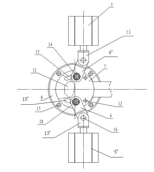
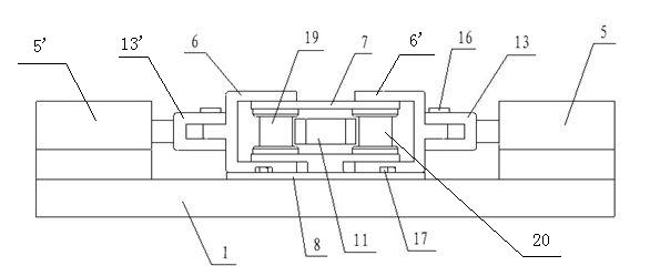
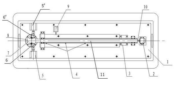
[0032] An embodiment of a pipe bender, such as Figure 1~3 As shown, it includes a workbench 1, a feed mechanism set on the workbench 1, a compression mechanism for pressing pipes, and a pipe bending mechanism for bending pipes. The feed mechanism includes a motor 2, a coupling 10. The lead screw 21 connected to the shaft coupling 10 and the nut seat push frame 22 driven by the lead screw 21. The nut seat push frame 22 includes a nut seat 35 and a nut 36 fixedly connected to the nut seat 35. The lead screw 21 slides Perforated in the hole 37 of the nut seat, the pipe bending mechanism includes a mandrel 11 arranged on the workbench and a first roller 19 and a second roller 20 vertically arranged on the workbench, the workbench includes a table top and The mandrel heads of the two rollers 19, 20 and mandrels are all arranged on the chassis 8, and the outer periph...


PUM


Abstract

The invention relates to a pipe bender, comprising a worktable, a feeding mechanism, a compacting mechanism and a pipe bending mechanism; the pipe bending mechanism comprises a mandrel fixed on the worktable, and a first roller and a second roller both of which are vertically arranged on the worktable; a plurality of guide structures are arranged on the worktable and located symmetrically on both sides of the mandrel head; the guide structures extend from the root part of the mandrel head to the tail end along the contour line of the mandrel head, and two extreme positions of the guide structures respectively correspond to the root part and the tail end of the mandrel head; the bottom parts of the two rollers are respectively slidably arranged on the corresponding guide structures; and the worktable further is provided with a driving mechanism used for respectively driving the two rollers to reciprocate between the two extreme positions of the guide structures so as to roll and bend the pipes. The invention further relates to a bending method using the pipe bender. The problem that the pipe bending mechanisms in the prior art bend the pipes only in one direction is solved.

Description

technical field [0001] The invention relates to a pipe bending machine and also relates to a bending method using the pipe bending machine. Background technique [0002] For heavy-duty tank trucks and coal trucks, in order to ensure safety, square tubes must be used for the penetrating beams. However, due to some technical difficulties in bending square tubes, most companies still use square tubes and parallel irons. This not only increases the cost, but also makes the entire vehicle body heavier and the risk factor increases. [0003] At present, the mechanical pipe bending industry often adopts bending methods such as push bending, pulling bending, winding bending, and pressing bending to process bends. The bending mechanisms used are all one-way bending mechanisms. If a pipe needs to be bent in multiple directions In this case, it can only be solved by changing the material, which is labor-intensive, and the process of changing the material affects the machining accuracy...

Claims


Application Information

Patent Timeline
IPC IPC(8): B21D9/10
Inventor 张丰收崔凤奎王晓强李兮蒈谢亚飞冯亚波高乐杨建玺薛进学
Owner HENAN UNIV OF SCI & TECH
Why Eureka
Try Eureka