
Conical arc plate drilling clamp tool

A drilling jig and arc-shaped plate technology, which is applied in the direction of drilling/drilling equipment, clamping, positioning devices, etc., can solve the problems that the machining accuracy of each hole of the conical arc-shaped plate cannot be satisfied at the same time, and achieve the goal of meeting the machining accuracy Effect

Active Publication Date: 2012-09-26
HARBIN JIANCHENG GRP
View PDF5 Cites 20 Cited by
  • Summary
  • Abstract
  • Description
  • Claims
  • Application Information

AI Technical Summary

Problems solved by technology

[0010] The purpose of the present invention is to solve the problem that the existing conical arc-shaped plate drilling jig cannot meet the machining accuracy of each hole of the conical arc-shaped plate, and further provide a conical arc-shaped plate drilling jig

Method used


Image

  • Conical arc plate drilling clamp tool
  • Conical arc plate drilling clamp tool
  • Conical arc plate drilling clamp tool

Examples


specific Embodiment approach 1

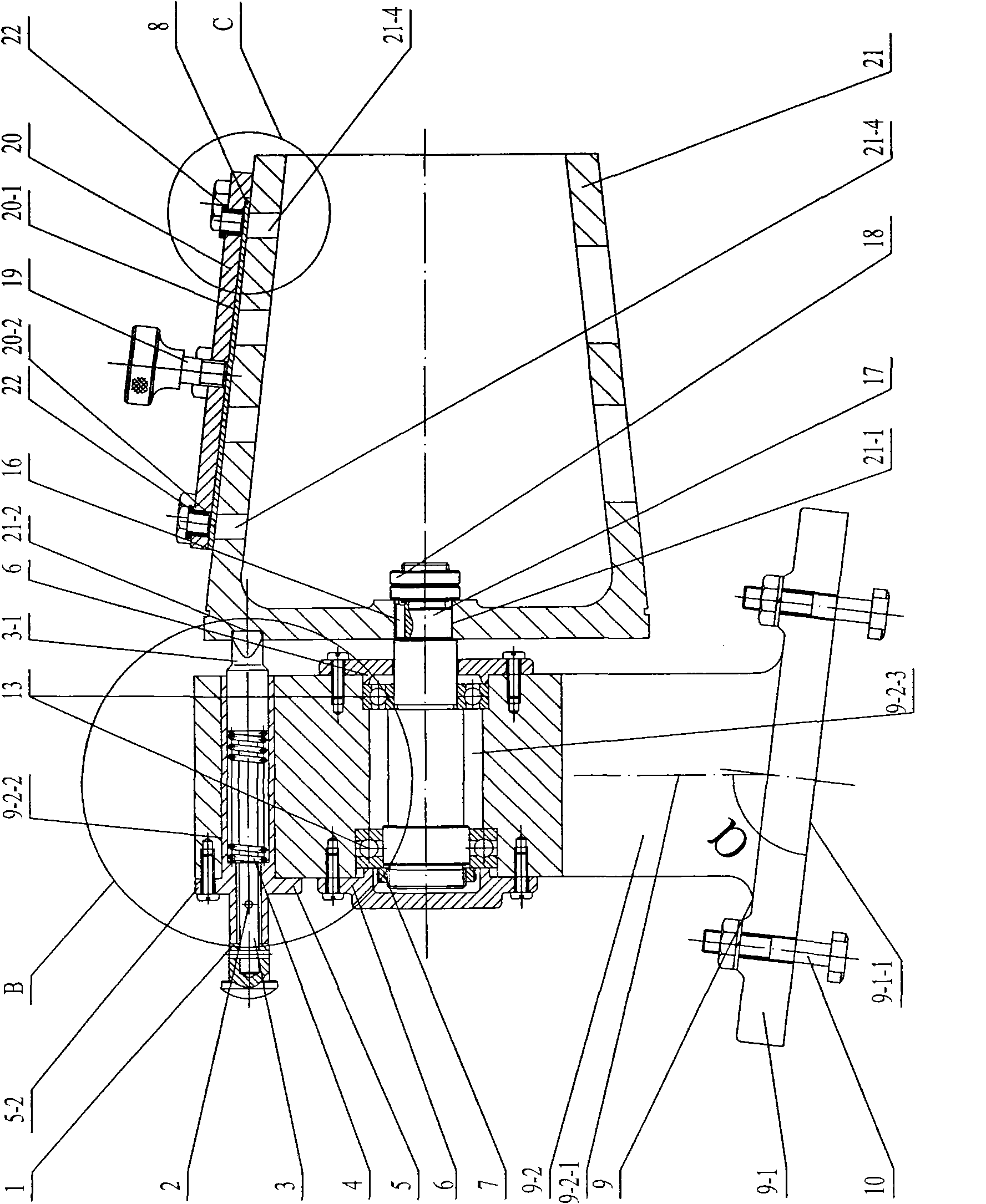
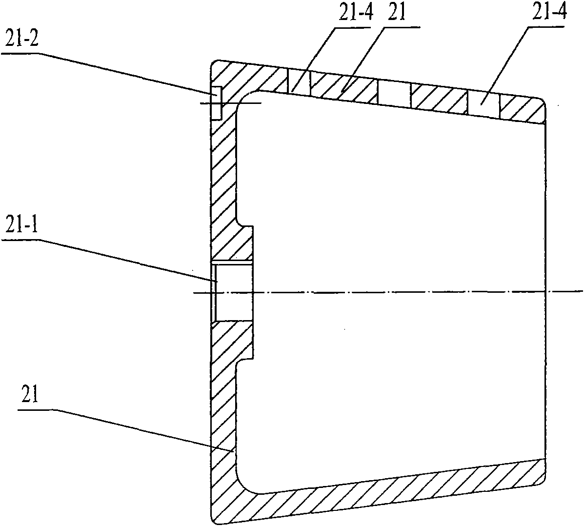
[0014] Specific implementation mode one: combine Figure 1 to Figure 10 Describe this embodiment, the tapered arc-shaped plate drilling jig tooling of this embodiment includes a pin handle 1, a latch 2, a positioning pin 3, a spring 4, a positioning pin cylinder 5, a first round nut 7, a placenta 9, a key 16, Step rotating shaft 17, second round nut 18, arc plate drilling mold 20, cone 21, two sealing covers 6 and two bearings 13, said placenta 9 is made of base 9-1 and base 9-1 It is composed of an integral upper body 9-2, and the acute angle α formed between the vertical line 9-2-1 of the upper body 9-2 and the bottom plane 9-1-1 of the base 9-1 is 83°. On the upper body 9-2, there are pin mounting holes 9-2-2 and shaft mounting holes 9-2-3 successively from top to bottom, and the pin mounting holes 9-2-2 and shaft mounting holes 9-2-3 are all along the Open in the horizontal direction, the center of the positioning pin cylinder 5 has a stepped hole 5-1, the positioning pin...

specific Embodiment approach 2

[0016] Specific implementation mode two: combination figure 2 The present embodiment will be described. The bearing 13 of the present embodiment is a single row radial ball bearing. Other compositions and connections are the same as in the first embodiment.

specific Embodiment approach 3

[0017] Specific implementation mode three: combination Figure 5 Describe this embodiment, the arc plate jig 20 of this embodiment is a 45# steel arc plate jig or a T8A arc plate jig. Other compositions and connections are the same as those in Embodiment 1 or Embodiment 2.


PUM


Abstract

The invention discloses a conical arc plate drilling clamp tool, relates to a drilling clamp tool for plate parts, and aims to solve the problem that the conventional conical arc plate drilling clamp tool cannot simultaneously meet the machining precision of various holes of the conical arc plate. An acute angle formed between a midperpendicular of an upper body and a bottom plane of the base is 83 degrees; a positioning pin is simply arranged in a pin mounting hole and is arranged in a positioning pin cylinder; a spring sleeve is arranged on the positioning pin; a stepped rotating shaft is arranged in a shaft mounting hole; a small diameter end of the stepped rotating shaft is connected with a central hole of a cone; an outer conical surface of the cone is consistent with an inner surface of the conical arc plate; a notch subjected to profile modeling of the conical arc plate is formed on the lower surface of an arc plate drill jig; a through hole is formed on the arc plate drill jig; a positioning groove is formed on an end face which is close to the upper body, of the cone; the arc plate drill jig is buckled on the outer conical surface of the cone; the conical arc plate is inserted into the notch; and a positioning column subjected to profile modeling on the positioning pin is inserted into the positioning groove. The conical arc plate drilling clamp tool is used for a conical arc plate drilling process.

Description

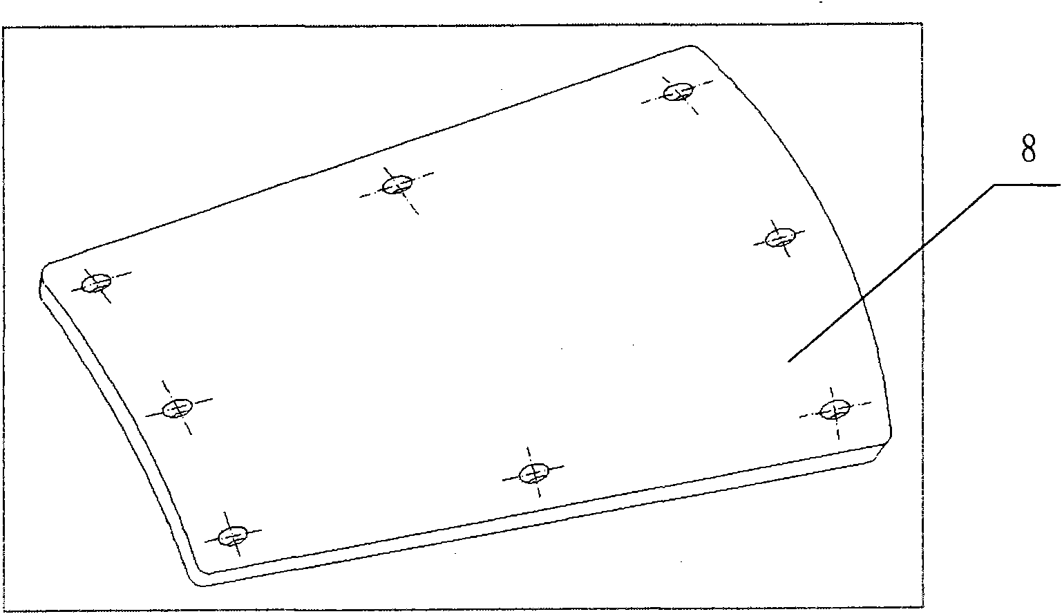
technical field [0001] The invention relates to a drilling fixture tooling for plate parts, which belongs to the technical field of mechanical processing. Background technique [0002] Conical curved plate (such as figure 1 , the thickness of the plate is 3mm) each connecting hole of the part is drilled before connecting with a certain part in the assembly, this processing method can only meet the production requirements of small batches or single assembly. In addition, the conical arc-shaped plate needs to be disassembled frequently in the process of debugging and measurement and control. The connection between the cover plate and the transition cabin is only for processing, which does not meet the size requirements marked on the product drawing, and cannot guarantee the interchangeability of various product parts. In mass production, if you do not mark them one by one, once they are mixed, it is easy to cause confusion that cannot be assembled; because it is equipped with...

Claims


Application Information

Patent Timeline
Patent Type & Authority Applications(China)
IPC IPC(8): B23B49/02B23Q3/06
Inventor 丁学彬张雯洁
Owner HARBIN JIANCHENG GRP
Learn More