
Turntable type tool fixture for machining glass molds

A technology for glass molds and fixtures, applied in the field of fixtures, can solve the problems of mold damage, troublesome maintenance and repair of power transmission mechanisms, and no technical enlightenment, and achieves the effect of saving time and facilitating replacement and maintenance.

Inactive Publication Date: 2012-09-26
ORI MOLD TECH SUZHOU
View PDF7 Cites 46 Cited by
  • Summary
  • Abstract
  • Description
  • Claims
  • Application Information

AI Technical Summary

Problems solved by technology

[0003] Before the technical solution of Chinese Invention Patent Application Publication No. CN101659015A (tooling fixture for processing glass moulds) was released, it was not limited to the aforementioned engraving, drilling and setting mold lifting holes , opening positioning slots, opening wear plate slots, processing vest eyes (ie hanging nail holes), milling triangles, inner and outer wires (ie milling arcs) and tapping holes, that is, tapping, etc. are usually performed by ordinary rather than Numerical control milling machines, drilling machines, and tapping machines are responsible for each, resulting in many workpiece turnover links, frequent clamping times, difficulty in ensuring glass mold quality, long processing time, low efficiency, and high labor intensity for workers. That is to say CN101659015A basically This technical problem has been solved, and the technical effect of lines 2-3 on page 3 of the manual has been objectively reflected
[0004] However, the above-mentioned CN101659015A still has the following shortcomings: one, because the turntable (the patent is called a rotary bed) needs to rotate freely under the drive of the power mechanism connected to the rotary shaft transmission. Therefore, only a pair of clamp arms on both sides of the mold platform clamp the mold, and there is a risk that the mold may escape from the end of the mold platform, thereby causing damage to the mold, and in the Y-axis direction of the machine tool (facing the operation Orientation is generally defined as the Y-axis direction) positioning does not give technical inspiration, if re-clamping is implemented after the mold escapes, on the one hand, the labor intensity of the workers will be increased and the work efficiency will be affected; on the other hand, it will be affected by the secondary clamping processing quality; secondly, since the machining center is usually not equipped with a power transmission mechanism for driving the turntable to rotate, in order to ensure power for the turntable, it is necessary to configure a power transmission mechanism on the machining center. However, due to the structure of the machining center itself is very It is compact and has limited space, so it is difficult to add a power transmission mechanism to the machining center, and the patent application scheme does not give corresponding technical inspiration; third, it is more troublesome and time-consuming to replace and repair the fixture Lengthy, because the turntable is connected to the power transmission mechanism on the machining center, so when the entire fixture is to be moved away from the machining center, it needs to go through complicated operations to release the transmission connection between the turntable and the power transmission mechanism; Fourth, the power transmission mechanism Maintenance and repairs are troublesome because it is difficult to move the power transmission mechanism out of the machining center, and the space available for maintenance work on the machining center is very limited

Method used


Image

  • Turntable type tool fixture for machining glass molds
  • Turntable type tool fixture for machining glass molds

Examples


Embodiment Construction

[0019] In order to enable the examiners of the patent office, especially the public, to understand the technical essence and beneficial effects of the present invention more clearly, the applicant will describe in detail the following in the form of examples, but none of the descriptions to the examples is an explanation of the solutions of the present invention. Any equivalent transformation made according to the concept of the present invention which is merely formal but not substantive shall be regarded as the scope of the technical solution of the present invention.

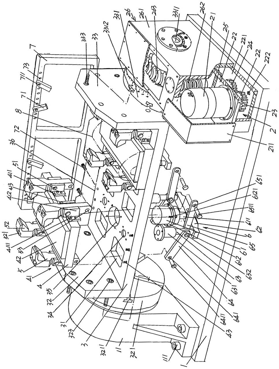
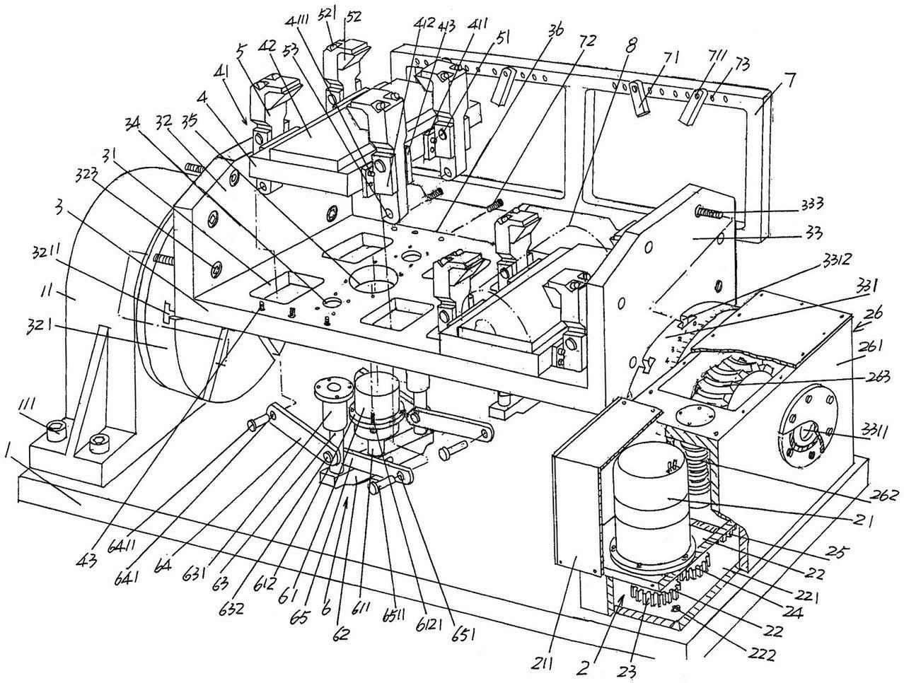
[0020] See figure 1 , a rectangular (cuboid in this embodiment) base plate 1 is given, and a bearing seat 11 is fixed at one end of the base plate 1, that is, the left end of the position shown in the figure, with a bearing seat fixing screw 111. There is no doubt that the bearing The seat 11 is provided with a bearing. A power transmission mechanism 2 is arranged at the other end of the base plate 1 , ...


PUM


Abstract

The invention discloses a turntable type tool fixture for machining glass molds, and belongs to the technical field of tool fixtures. The turntable type tool fixture comprises a base plate, a power transmission mechanism, a turntable, at least one mold platform, a clamp arm opening mechanism and a mold end surface positioning frame, wherein a bearing block is arranged at one end of the base plate, the power transmission mechanism is disposed at the other end of the base plate, one end of the turntable is supported on the bearing block, the other end of the turntable is connected with the power transmission mechanism, the mold platforms are fixed to the middle of the turntable, a pair of clamp arm seats is respectively fixed to two sides of each mold platform, a clamp arm is hinged on each clamp arm seat, the clamp arm opening mechanisms are hinged with the clamp arms, the mold end surface positioning frame is fixed to one side of the turntable, and clamp arm avoiding holes are arranged on the turntable. The turntable type tool fixture for machining glass molds has the advantages that the glass molds are prevented from shifting from end surfaces of the mold platform during machining, the power transmission mechanism is in transmission connection with the turntable without a machining center used as a carrier, the trouble of secondary modification for the machining center is avoided, replacement and maintenance are facilitated, time can be saved, work intensity of maintenance staff is relieved, and work efficiency is improved.

Description

technical field [0001] The invention belongs to the technical field of tooling fixtures, and in particular relates to a turntable-type tooling fixture for processing glass moulds. Background technique [0002] Fixtures play a very important role in the production process of industrial products, and the production of glass molds is no exception. The so-called tooling fixture refers to special equipment or tools used to clamp or position the workpiece in machining to meet certain process requirements. It usually needs to meet the requirements of no interference during product production, accurate and reliable positioning, and convenient operation. Require. Because the tooling fixture has the exclusive characteristics of manufacturing a certain product, the degree of generalization is extremely low. It is often made by the manufacturer of mechanical products in a tailor-made way, and most of the manufacturers of glass molds are equipped with various tooling in a self-made way....

Claims


Application Information

Patent Timeline
Patent Type & Authority Applications(China)
IPC IPC(8): B23Q1/25B23Q3/00B23Q5/34
Inventor 戈剑鸣
Owner ORI MOLD TECH SUZHOU
Features
  • Generate Ideas
  • Intellectual Property
  • Life Sciences
  • Materials
  • Tech Scout
  • Unparalleled Data Quality
  • Higher Quality Content
  • 60% Fewer Hallucinations
Learn More