Rotating-tower-type automatic tool changer of numerical control machine tool

A technology of automatic tool change and CNC machine tools, applied in positioning devices, metal processing machinery parts, clamping, etc., can solve the problems of difficult installation and maintenance, low work efficiency, and short service life, so as to improve reliability, The effect of reducing tool change time

Inactive Publication Date: 2012-09-26
FOSHAN PRATIC CNC SCI & TECH
View PDF5 Cites 14 Cited by
  • Summary
  • Abstract
  • Description
  • Claims
  • Application Information

AI Technical Summary

Problems solved by technology

[0002] At present, the turret-type automatic tool change devices of CNC machine tools at home and abroad all use transmission mechanisms such as tool disc separation mechanisms, connecting rod mechanisms, and conveyor belts to transmit power and realize certain special actions. This structural design has its shortcomings Because of: complex structure, high working noise, many mechanical failures, serious wear, difficult installation and maintenance, long installation and maintenance time, resulting in low work efficiency, high cost and short service life

Method used


Image

  • Rotating-tower-type automatic tool changer of numerical control machine tool
  • Rotating-tower-type automatic tool changer of numerical control machine tool
  • Rotating-tower-type automatic tool changer of numerical control machine tool

Examples


Embodiment Construction

[0011] The present invention will be further described below in conjunction with specific examples.

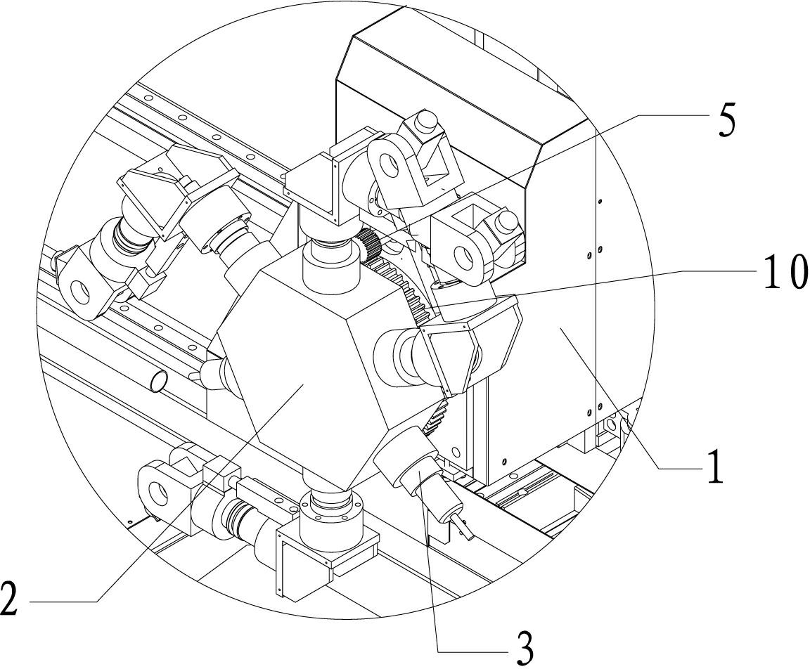
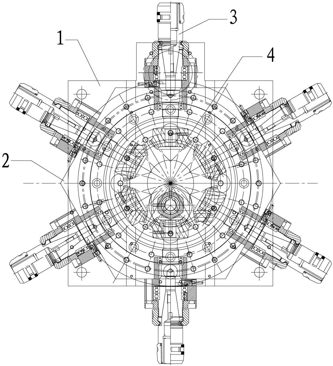
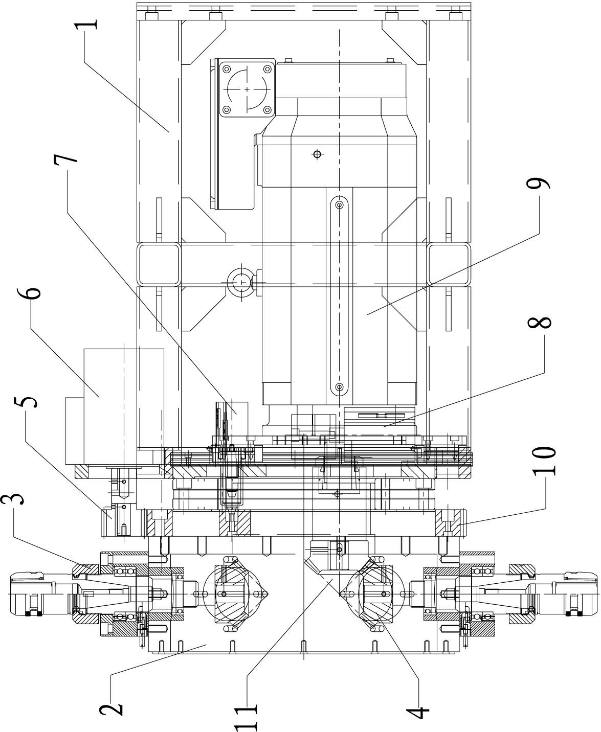
[0012] See attached figure 1 to attach image 3 As shown, the turret-type automatic tool changer of the CNC machine tool described in this embodiment includes a tool holder 1, a turret head 2, a spindle head 3, a spindle bevel gear 4, a tool changer gear 5, a tool changer motor 6, Positioning cylinder 7, lifting cylinder 8, spindle motor 9, wherein, the turret head 2 described in the present embodiment is a hexagonal turret head, which is rotatably assembled on the turret head mounting position at one end of the tool rest 1, and the tool change motor 6 is horizontally installed on the top of the tool rest 1, and a tool change gear 5 is mounted on the rotating shaft head of the tool change motor 6, and at the same time, one end of the turret head 2 connected with the tool rest 1 is correspondingly installed with the above-mentioned change gear. The gear plate 10 meshed with t...


PUM


Abstract

The invention provides a rotating-tower-type automatic tool changer of a numerical control machine tool. The rotating-tower-type automatic tool changer comprises a tool rest, a rotating tower head, spindle heads, a spindle bevel gear, a tool changing gear, a tool changing motor, a positioning cylinder, an elevating cylinder and a spindle motor, wherein the rotating tower head is installed at a rotating tower head installing position at one end of the tool rest; the tool changing motor is installed at the top of the tool rest; the tool changing gear is installed on a rotating shaft head; a gear disc which is meshed with the tool changing gear is installed at one end of the rotating tower head; a plurality of positioning holes are formed on the gear disc; a plurality of spindle heads are distributed along the circumferential direction of the rotating tower head; one end of each spindle head stretching into the rotating tower head is connected with the spindle bevel gear; the positioning cylinder is installed inside the tool rest; the piston rod head of the positioning cylinder stretches out of the tool rest so as to be matched with the positioning holes; the spindle motor is installed inside the tool rest and is driven to ascend and descend by the elevating cylinder arranged below the spindle motor; and the rotating shaft head of the spindle motor is equipped with the bevel gear matched with the spindle bevel gear. According to the tool changing device, the spindle head is changed by using the transposition of the rotating tower head, so that the automatic tool changing function is realized.

Description

technical field [0001] The invention relates to the technical field of numerically controlled machine tools, in particular to a turret-type automatic tool changing device for numerically controlled machine tools. Background technique [0002] At present, the turret-type automatic tool change devices of CNC machine tools at home and abroad all use transmission mechanisms such as tool disc separation mechanisms, connecting rod mechanisms, and conveyor belts to transmit power and realize certain special actions. This structural design has its shortcomings The disadvantages are: complex structure, high working noise, many mechanical failures, serious wear, difficult installation and maintenance, and long installation and maintenance time, resulting in low work efficiency, high cost, and short service life. Contents of the invention [0003] The purpose of the present invention is to overcome the deficiencies of the prior art and provide a turret-type automatic tool changer for...

Claims


Application Information

Patent Timeline
Patent Type & Authority Applications(China)
IPC IPC(8): B23Q3/155
Inventor 李爱军
Owner FOSHAN PRATIC CNC SCI & TECH
Why Eureka
Try Eureka