
Forklift truck

A forklift truck and front frame technology, which is applied to motor vehicles, lifting devices, transportation and packaging, etc., can solve the problems of reduced operation quality and work efficiency, short front overhang distance, and reduced cargo stability, so as to improve operation The effect of quality and work efficiency, accurate loading and unloading of goods, and improvement of braking force

Active Publication Date: 2012-09-26
FUJIAN FUDA MACHINERY
View PDF7 Cites 5 Cited by
  • Summary
  • Abstract
  • Description
  • Claims
  • Application Information

AI Technical Summary

Problems solved by technology

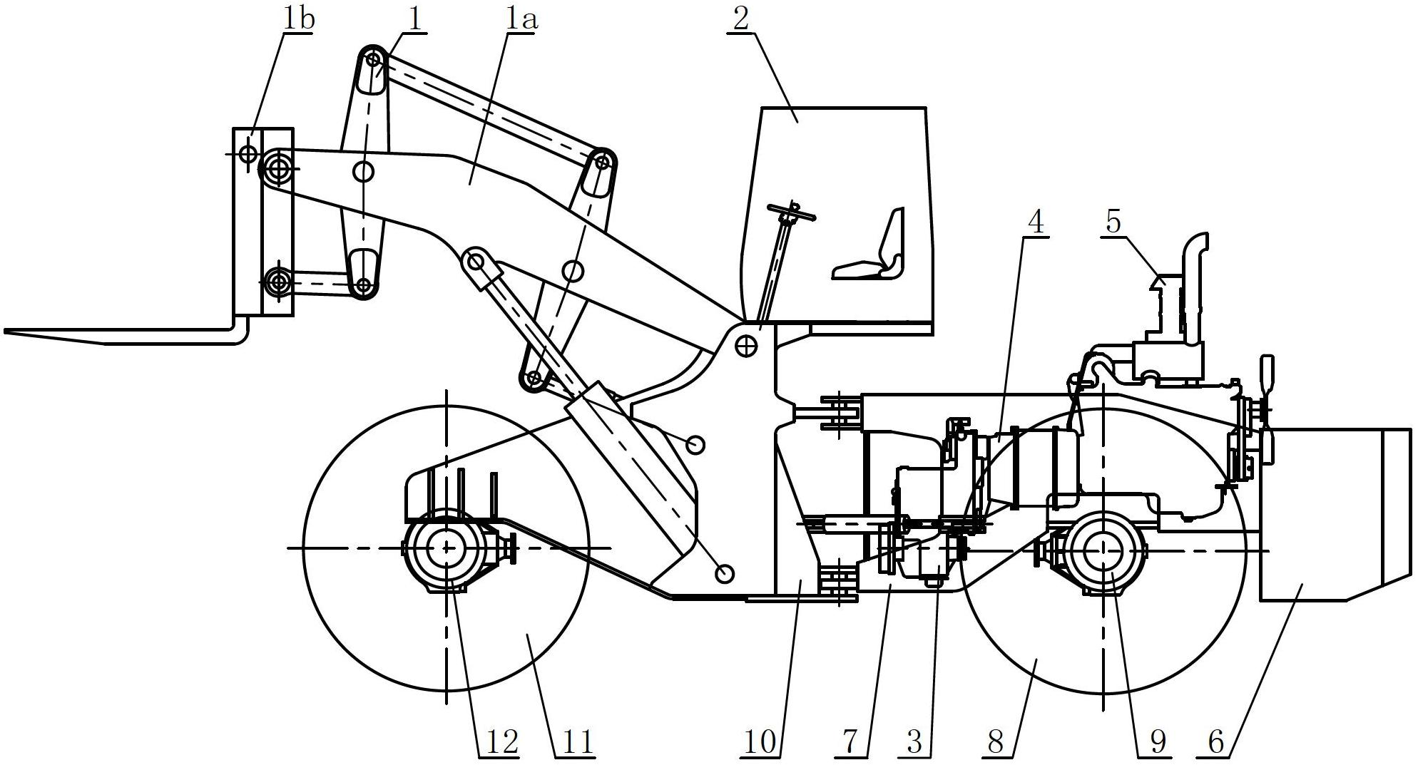
These forklift trucks exist together: first, the cab installed on the rear frame and the working device installed on the front frame will rotate each other and the front and rear distance between the two is relatively large, resulting in the driver's field of vision being relatively narrow. Poor, thus reducing the quality of work and work efficiency; Second, the brake device is composed of a brake disc and two brake calipers, a total of four brake discs and eight brake calipers in the vehicle, under heavy load (Generally refers to the weight of the loaded cargo exceeding 20 tons) When driving fast or parking on a ramp, its braking force can no longer meet the requirements of rapid and reliable braking, and there are potential safety hazards; third, the machine has a single operation function
In addition, the forklift truck described in the Chinese patent application number 200910111391.3 has a gantry-type lifting mechanism with a short front suspension distance, which is inconvenient for cargo loading and unloading; the forklift truck described in the Chinese patent application number 201110217317. The mechanism is a six-link structure. When loading and unloading cargo, the inclination angle of the cargo will change accordingly with the change of the lifting height, and the stability of the cargo will decrease.

Method used


Image

  • Forklift truck
  • Forklift truck
  • Forklift truck

Examples


Embodiment 1

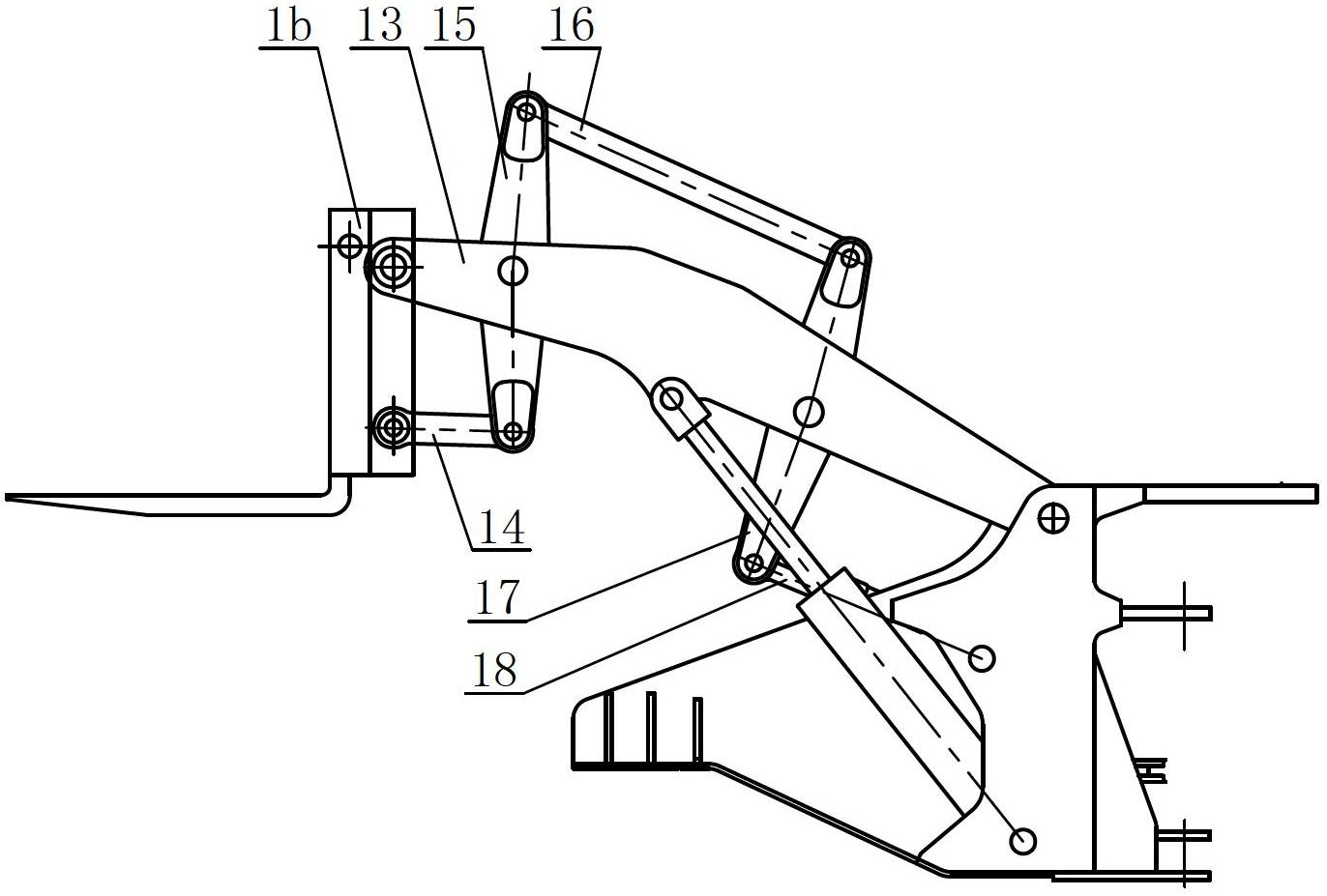
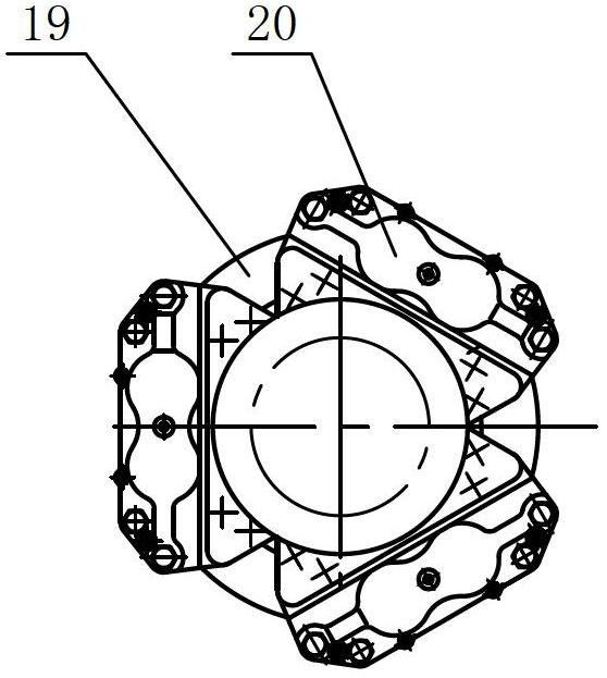
[0020] Such as figure 1 , 2 The shown forklift truck includes a front frame 10, a rear frame 7, a working device 1, a cab 2, an engine 5, a torque converter 4, a gearbox 3, front and rear drive axles 12, 9, and is characterized in that The working device 1 and the cab 2 are installed on the front frame 10, the engine 5, the torque converter 4, the gearbox 3 and the counterweight 6 are installed on the rear frame 7; the lifting mechanism 1a of the working device 1 is eight connecting rods Structure: The braking device is symmetrically installed at both ends of the drive axle, and each braking device is composed of a brake disc 19 and three brake calipers 20, and the three brake calipers 20 are evenly distributed along the circumference of the brake disc 19.

[0021] The working device 1 is installed in front of the front frame 10. The working device 1 is composed of a lifting mechanism 1a and an attachment 1b. The attachment 1b in this embodiment is a fork assembly; one end of...

Embodiment 2

[0028] Such as Figure 4 For the shown forklift truck, its attachment 1b is replaced by a bucket assembly.

[0029] The parts not described in this embodiment are the same as those in Embodiment 1.


PUM


Abstract

The invention relates to a forklift truck, comprising a front frame, a rear frame, a working device, a steering room, an engine, a torque converter, a transmission gear, a front drive bridge and a rear drive bridge. The forklift truck is characterized in that the working device and the steering room are mounted on the front frame; the engine, the torque converter, the transmission gear and a balancing weight are mounted on the rear frame; a lift mechanism of the working device is an eight-bar mechanism; brake devices are symmetrically mounted at both ends of the drive bridge; and each of the brake devices consists of a brake disc and three brake calipers which are evenly distributed along the circumference of the brake disc. The forklift truck has the advantages of wide vision for drivers, stability in cargo loading and unloading, high quality and working efficiency, reliability in braking and multiple functions.

Description

technical field [0001] The invention relates to a construction machine, in particular to a forklift. Background technique [0002] Existing forklift trucks, such as the forklift trucks described in the Chinese patents whose application numbers are 200910111391.3 and 201110217317.7, have working devices installed on the front frame, and cabs, engines, torque converters, gearboxes, and counterweights are installed on the rear trucks. on the shelf. These forklift trucks exist together: first, the cab installed on the rear frame and the working device installed on the front frame will rotate each other and the front and rear distance between the two is relatively large, resulting in the driver's field of vision being relatively narrow. Poor, thus reducing the quality of work and work efficiency; Second, the brake device is composed of a brake disc and two brake calipers, a total of four brake discs and eight brake calipers in the vehicle, under heavy load (Generally refers to ...

Claims


Application Information

Patent Timeline
IPC IPC(8): B66F9/06B66F9/075B62D53/00
Inventor 柯贤玄郑为鼎黄自峰谢小健
Owner FUJIAN FUDA MACHINERY
Learn More