Simple sliding grid anti-blocking gully

A kind of gully, simple technology, applied in waterway systems, water supply devices, drainage structures, etc., can solve the problems of small drainage capacity, affecting the sight of vehicles, reducing the strength of the road surface layer, etc., to restore the water intake capacity, reduce the ground Effects of standing water and expressway rain

Active Publication Date: 2012-09-26
SHANGHAI URBAN CONSTR DESIGN RES INST GRP CO LTD
View PDF9 Cites 11 Cited by
  • Summary
  • Abstract
  • Description
  • Claims
  • Application Information

AI Technical Summary

Problems solved by technology

[0004] 1. The accumulated water will form splashes under the action of driving, which will affect the sight of subsequent vehicles
[0005] 2. Asphalt mixture soaked in water for a long time is easy to peel off and reduce the strength of road surface
[0006] 3. When the water accumulates to a certain thickness, it will form "water floating" when driving, causing the wheels to slip
[0007] 4. During heavy rain, it is very easy to cause a large area of ​​water to form on the road surface, resulting in traffic paralysis and great economic losses
[0008] However, at present, the old urban areas of most cities still use the traditional single vertical grate water intake or flat grate water intake. Due to the influence of the terrain and the blockage of garbage and debris, the water flow area of ​​the orifice of the rainwater outlet of many roads is relatively small, and the water is collected when it rains. Slower, less drainage capacity, single type, and serious blockage and damage
Once the drainage capacity of the rainwater outlet is insufficient, even if the design capacity of the pipeline is high, it will cause water accumulation on the road surface, which will not be able to play the role of the design capacity of the pipeline

Method used


Image

  • Simple sliding grid anti-blocking gully
  • Simple sliding grid anti-blocking gully
  • Simple sliding grid anti-blocking gully

Examples


Embodiment Construction

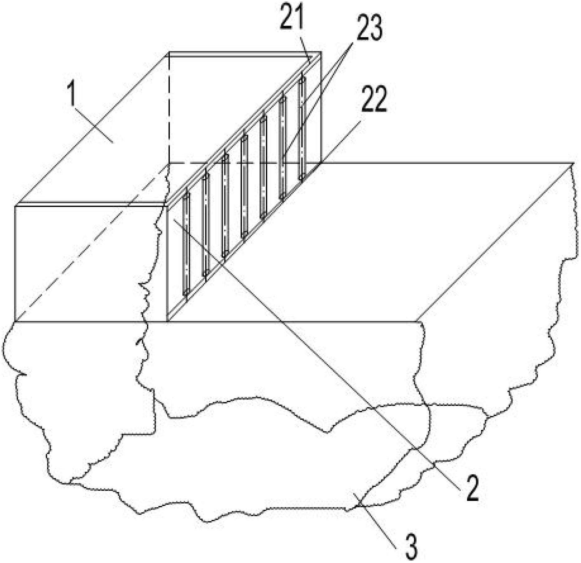
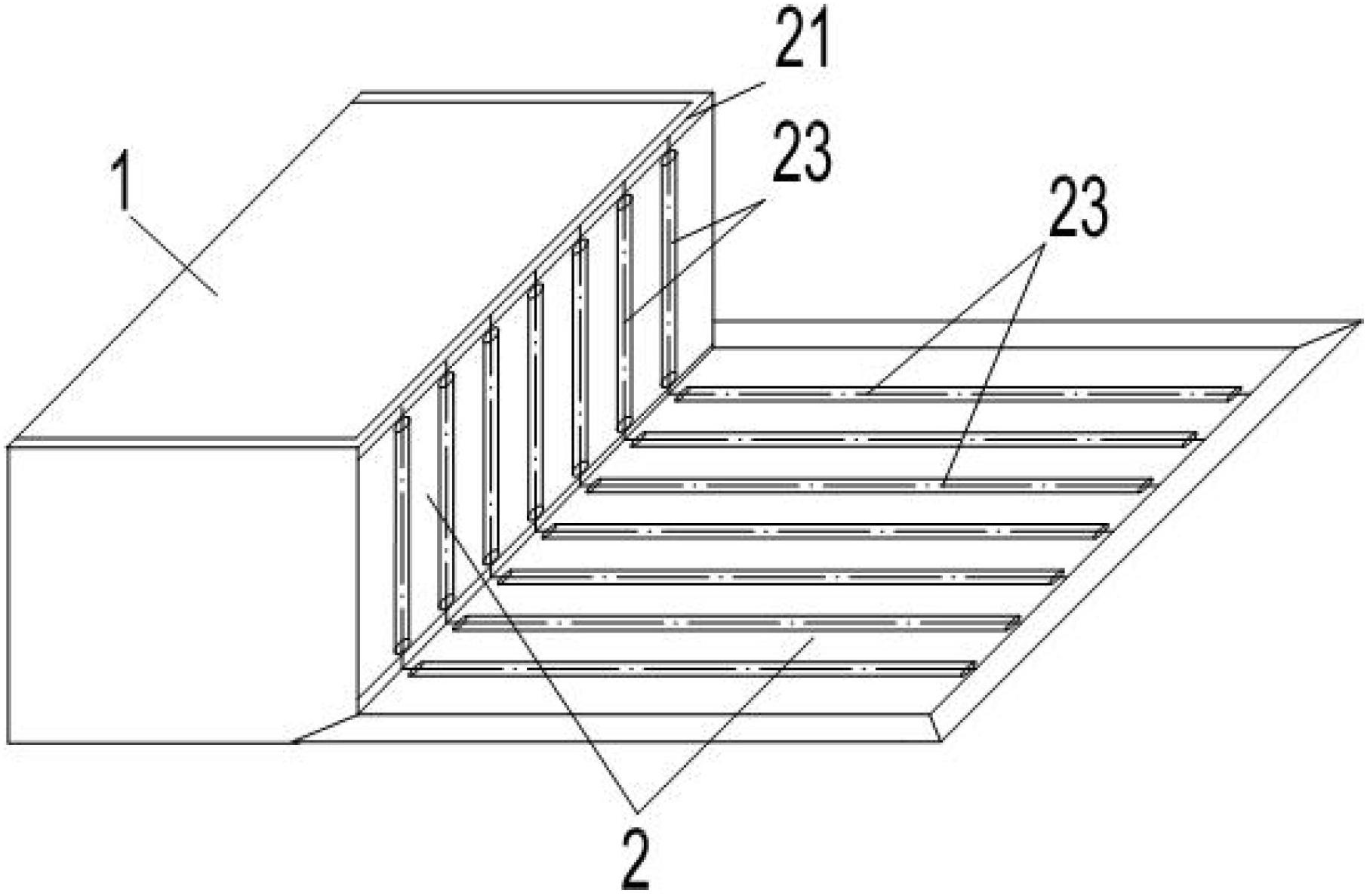
[0023] Such as figure 1 As shown, a specific embodiment of the simple sliding grid anti-blocking gully of the present invention mainly includes a gully body 1 and a gully cover 2 . The gully body 1 is a frame structure, and the part where the gully cover 2 is provided is an opening. The bottom of the gully body 1 is also provided with a dirt intercepting hanging basket 3 .

[0024] The upper part of the gully cover 2 is provided with an upper guide rail 21 , and the lower part is provided with a lower guide rail 22 . Both ends of the upper guide rail 21 are rotatably connected to the gully cover 2 through sliding steel balls (not shown in the figure). The lower guide rail 22 is separated from the gully body 1 .

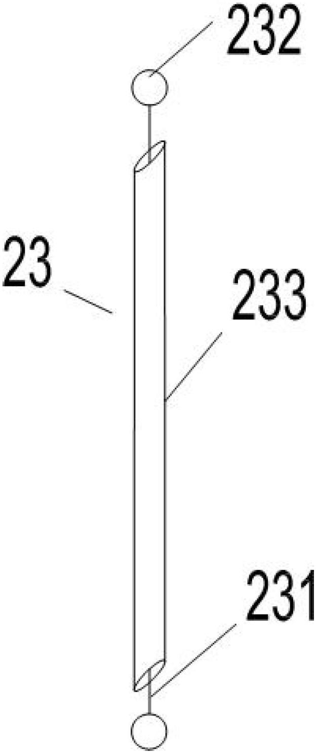
[0025] Several sliding grill bars 23 are slidably arranged between the upper guide rail 21 and the lower guide rail 22 . Such as figure 2 As shown, each sliding grating bar 23 includes a central rod 231 with steel balls 232 at both ends, and a hollow cylindrical...


PUM


Abstract

The invention discloses a simple sliding grid anti-blocking gully, which mainly comprises a gully body and a gully cover. An upper guide rail is arranged on the upper part of the gully cover, and a lower guide rail is arranged on the lower part of the gully cover; a plurality of sliding grids are arranged between the upper guide rail and the lower guide rail in a sliding mode; and each sliding grid comprises a center rod, wherein a steel ball is arranged at each of two ends of the center rod, and a rolling sleeve is sleeved on the center rod. The sliding grids are arranged on the gully cover, and the sliding grids can rotate under common working conditions, so the gully is difficultly blocked by garbage. When the gully is blocked or rainstorm is predicted, the sliding grids can be moved away through the upper guide rail and the lower guide rail, and the opening on the gully cover is opened, so that the garbage is flushed to a pollutant intercepting hanging basket together with rainwater, the water inlet capability of the gully is recovered, and the technical aims of quickly transferring rainwater on roads and reducing accumulated water on the ground during the rainstorm are fulfilled; and the gully has the advantages of simple structure, convenience in implementation and the like.

Description

technical field [0001] The invention relates to the technical field of water supply and drainage, in particular to a simple sliding grille to prevent blocking of rainwater outlets. Background technique [0002] The stormwater outlet is an important part of the urban drainage system. It is not only the bottleneck of urban pipelines collecting rainwater runoff, but also the primary channel for urban non-point source pollutants to enter the water environment. Therefore, the stormwater outlet occupies an important position in the urban drainage system. [0003] The rainwater outlet, also known as the rainwater collection well, is a facility for the pipeline drainage system to collect surface water. It is generally composed of water inlet grates, well bodies, and water collection branch pipes. The rain outlet discharges rainwater into the main pipe through the water collection branch pipe. It is an auxiliary structure of the urban drainage system and an important part of urban ro...

Claims


Application Information

Patent Timeline
Patent Type & Authority Applications(China)
IPC IPC(8): E03F5/06
Inventor 张显忠黄瑾刘佳伟
Owner SHANGHAI URBAN CONSTR DESIGN RES INST GRP CO LTD
Why Eureka
Try Eureka