Dual-clutch transmission for hybrid power

A dual-clutch, hybrid technology, applied in the direction of transmission, belt/chain/gear, mechanical equipment, etc., can solve the problems of high CVT cost, complex AT structure, long axial dimension, etc., to improve economic performance and internal structure Compact, performance-enhancing effects

Active Publication Date: 2012-09-26
ZHEJIANG GEELY AUTOMOBILE RES INST CO LTD +1
8 Cites 17 Cited by

AI-Extracted Technical Summary

Problems solved by technology

[0004] The existing technology has the following deficiencies: the AT structure is complicated and the efficiency is low; the cost of the CVT...

Abstract

The invention provides a dual-clutch transmission for hybrid power, belongs to the technical field of automotive transmissions and solves the technical problem that transmissions in the prior art are low in operating efficiency and the like. The dual-clutch transmission for hybrid power comprises a motor, an engine, a first input shaft, a second input shaft and an output shaft. The first input shaft is connected with an output end of the motor. The second input shaft is connected with an output end of the engine. A first drive gear is fixed on the first input shaft. A second drive gear is sleeved on the second input shaft. The first input shaft is connected with the second input shaft through a one-way clutch. The second input shaft is connected with the engine through a first double clutch. The second drive gear is fixed to the double clutch peripherally. A second double clutch and a third drive gear which can be connected with a differential are arranged on the output shaft. A first driven gear and a second driven gear are arranged on two sides of the second double clutch. The first driven gear and the second driven gear are meshed with the first drive gear and the second drive gear. The dual-clutch transmission for hybrid power has the advantages of high operating efficiency and the like.

Application Domain

Technology Topic

Image

  • Dual-clutch transmission for hybrid power
  • Dual-clutch transmission for hybrid power

Examples

  • Experimental program(1)

Example Embodiment

[0020] The following are specific embodiments of the present invention and the accompanying drawings to further describe the technical solutions of the present invention, but the present invention is not limited to these embodiments.
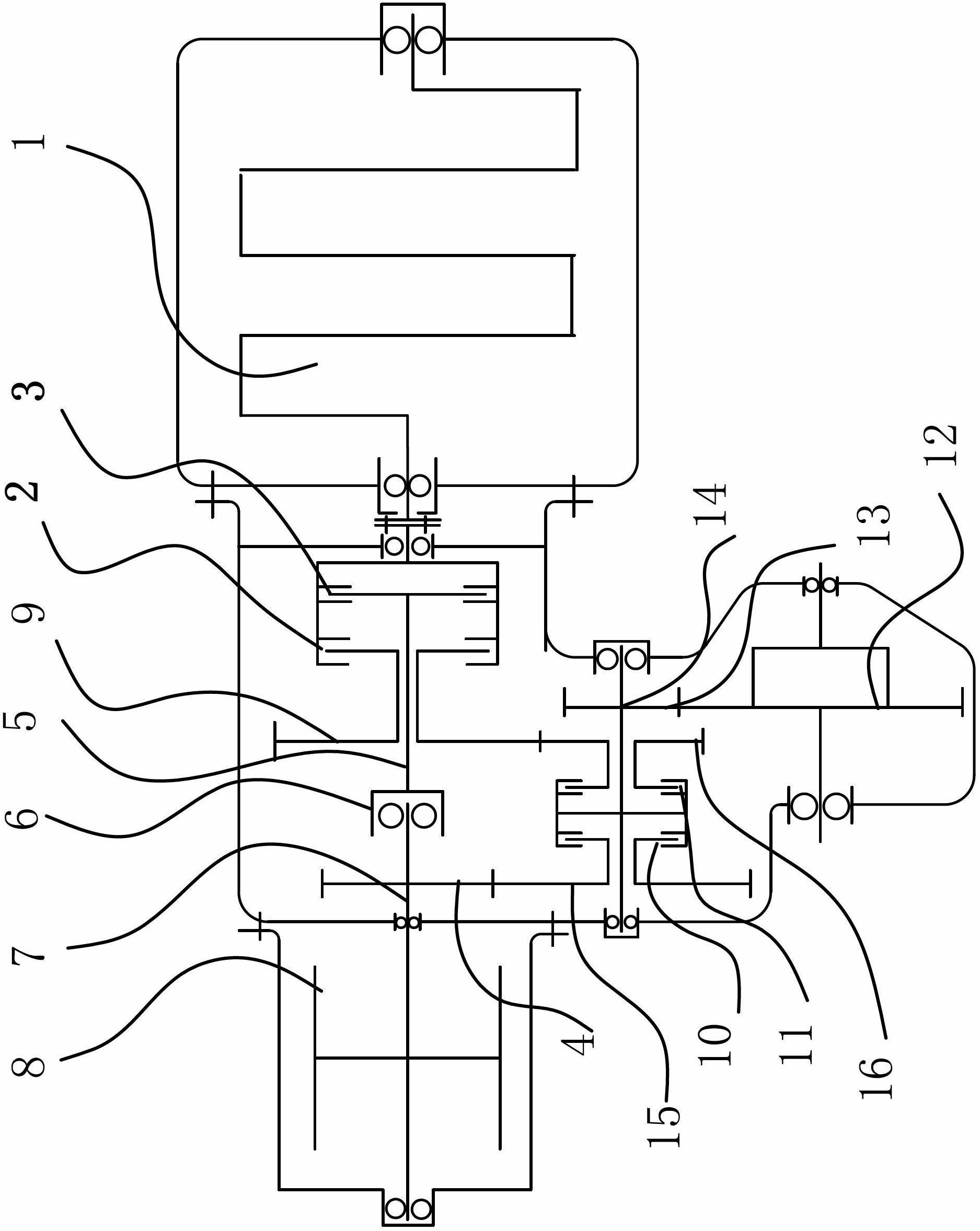
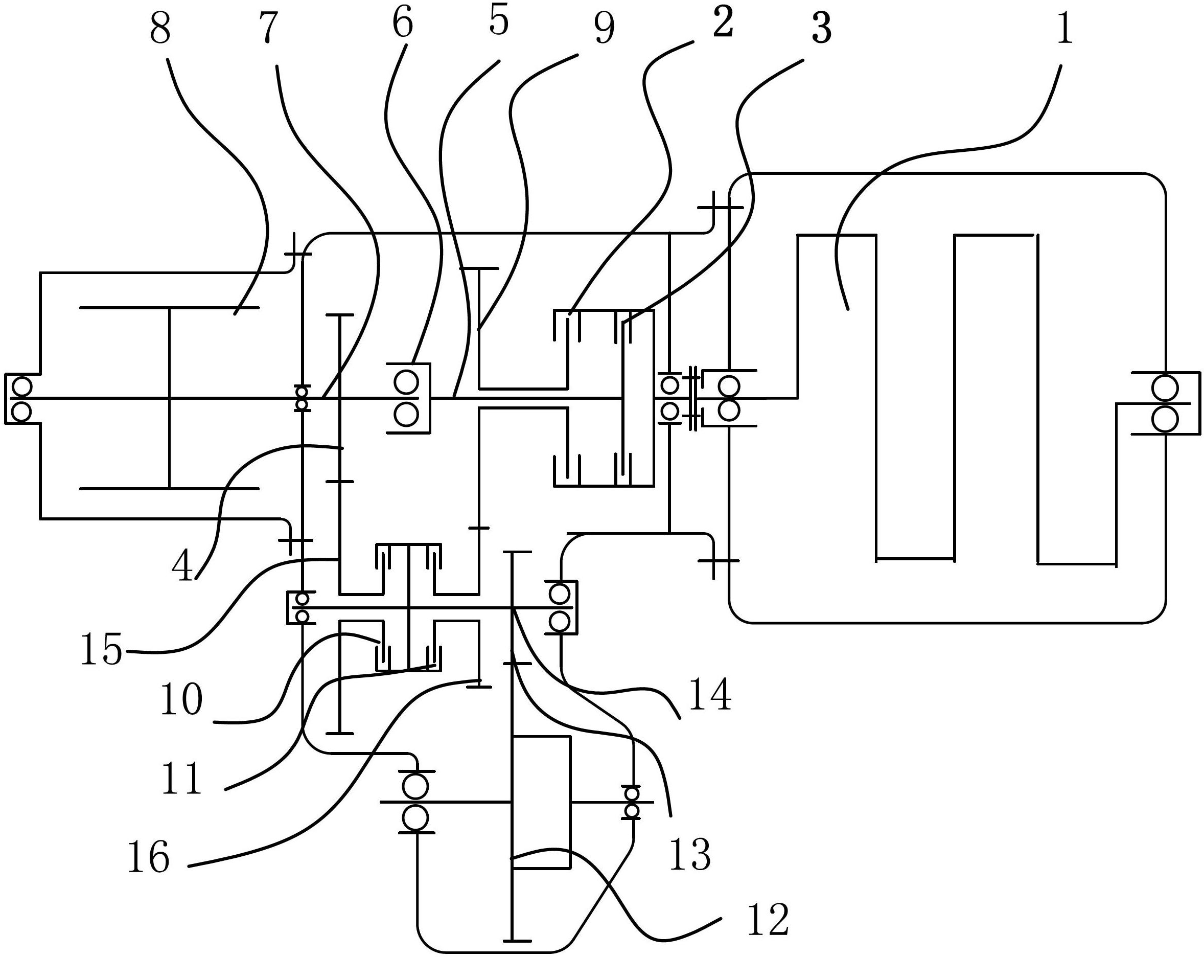
[0021] like figure 1 As shown, the dual clutch transmission for this hybrid power includes an electric motor 8, an engine 1, an input shaft 7, an input shaft 2 5 and an output shaft 14, the input shaft 1 7 is connected to the output end of the electric motor 8, and the input shaft 2 5 and The output ends of the engine 1 are connected, and the output end of the engine 1, the first input shaft 7, the second input shaft 5 and the output end of the electric motor 8 are all coaxially arranged. The input shaft one 7 is fixed with a driving gear one 4, the input shaft two 5 is sleeved with a driving gear two 9, the input shaft one 7 and the input shaft two 5 are connected by a one-way clutch 6, and the input shaft two 5 is connected with the engine. 1 is connected by a double clutch one-phase, the double clutch one packs the clutch one 2 and the second clutch 3, the clutch one 2 and the driving gear two 9 are fixed circumferentially, the clutch one 2 and the clutch two 3 are connected with the input shaft, The second clutch 3 is also connected to the output end of the engine 1 . The output shaft 14 is provided with a dual clutch 2 and a driving gear 3 that can be connected with the differential 12. The dual clutch 2 includes a clutch 3 10 and a clutch 4 11. Both sides of the dual clutch 2 are respectively provided with a driven gear 1 15 and a slave gear 1 . The second driven gear 16, the third clutch 10 and the driven gear one 15 are circumferentially fixed, the clutch four 11 and the driven gear two 16 are circumferentially fixed, and the driven gear one 15 and the driven gear two 16 are sleeved on the output shaft 14. , and the driven gear one 15 and the driven gear two 16 mesh with the driving gear one 4 and the driving gear two 9 respectively, the driven gear one 15 and the driven gear two 16 are respectively circumferentially fixed with the double clutch two, and from The diameter and number of teeth of the first driven gear 15 are larger than those of the second driven gear 16 , the diameter and number of teeth of the second driven gear 16 are larger than those of the third driving gear, and the diameter and number of teeth of the first driving gear 4 are smaller than those of the second driving gear 9 .
[0022] The working principle of the device is as follows: when the vehicle is in a parking state, both the first dual clutch and the second dual clutch are in a normally open state, that is, in a disengaged state, and do not transmit power. Only when the corresponding clutch is engaged, the power is transmitted. When the vehicle starts, the input shaft 1 7 is mainly driven by the motor 8 to rotate, and the engine 1 drives the input shaft 2 5 to provide the corresponding hybrid power supply for the input shaft 1 7 through the one-way clutch 6, using the dual input mode. When the vehicle enters a steady state, the one-way clutch 6 is switched, and the engine 1 works alone through the double clutch to drive the input shaft to rotate. At this time, the engine 1 works in a steady state, and the economy is the best. When the vehicle is braked, once the dual clutch is disconnected, the output shaft 14 reversely charges the electric motor 8 through the second dual clutch. When the vehicle reverses, the input shaft 7 is mainly driven by the electric motor 8 in the reverse direction to realize the reverse gear.
[0023] The specific embodiments described herein are merely illustrative of the spirit of the invention. Those skilled in the art to which the present invention pertains can make various modifications or additions to the described specific embodiments or substitute in similar manners, but will not deviate from the spirit of the present invention or go beyond the definitions of the appended claims range.

PUM

no PUM

Description & Claims & Application Information

We can also present the details of the Description, Claims and Application information to help users get a comprehensive understanding of the technical details of the patent, such as background art, summary of invention, brief description of drawings, description of embodiments, and other original content. On the other hand, users can also determine the specific scope of protection of the technology through the list of claims; as well as understand the changes in the life cycle of the technology with the presentation of the patent timeline. Login to view more.

Similar technology patents

Combined desulphurization deamination technology for coke oven gas

ActiveCN103468326AImprove economic performanceCombustible gas purificationAmmonium sulfateCoke oven gas
Owner:BEIJING SJ ENVIRONMENTAL PROTECTION & NEW MATERIAL CO LTD

Encoder structure

InactiveCN103722255ASimple structureImprove economic performanceThread cutting auxillary apparatusEngineeringFlange
Owner:WUXI JINGHUA HEAVY IND EQUIP MFG

Power shunting hybrid power coupling mechanism and control method thereof

PendingCN110303873AOptimize workspaceImprove economic performanceHybrid vehiclesGas pressure propulsion mountingClutchDouble row
Owner:江门宇度科技有限责任公司

Technology used for desulphurization deamination of coke oven gas

ActiveCN103468325AImprove economic performanceIron oxides/hydroxidesAmmonium sulfatesAmmonium sulfateCoke oven gas
Owner:BEIJING SJ ENVIRONMENTAL PROTECTION & NEW MATERIAL CO LTD

Automatic control method and automatic control device of water valve of surface treatment rinsing bath

InactiveCN101624704BImprove economic performanceThe Significance and Social Benefits of Significant Water Saving and Environmental ProtectionControlling ratio of multiple fluid flowsChemical variable controlAutomatic controlEngineering
Owner:ZTE CORP SHENZHEN CITY

Classification and recommendation of technical efficacy words

  • Improve economic performance
  • Energy saving

Refrigeration system for aircraft

InactiveCN102506514AReduce energy consumptionImprove economic performanceSpace heating and ventilation safety systemsSpace heating and ventilation control systemsBleed airProcess engineering
Owner:COMAC +1

Airplane cockpit windshield structure with sun shading function

InactiveCN105584620AReduce weightImprove economic performanceAircraft accessoriesFuselage insulationHeating filmAirplane
Owner:XIAN AIRCRAFT DESIGN INST OF AVIATION IND OF CHINA
Why Eureka
Try Eureka