Filtering device

A filter device and filter technology, which is applied in the direction of connection devices, waveguide devices, electrical components, etc., can solve the problems that the high-order harmonic suppression degree cannot meet the requirements, the insertion loss is large, and the high suppression degree cannot be obtained.

Active Publication Date: 2012-09-26
HUAWEI TECH CO LTD
View PDF2 Cites 16 Cited by
  • Summary
  • Abstract
  • Description
  • Claims
  • Application Information

AI Technical Summary

Problems solved by technology

[0005] In order to overcome the above-mentioned defects of the TE01 mode dielectric filter, two solutions have been proposed in the prior art: one is to add a metal resonator at the port of the TE01 mode dielectric filter, which can make the higher harmonic frequency and the passband The distance becomes farther, but the suppression of high-order harmonics still does not meet the requirements, and the inser

Method used


Image

  • Filtering device
  • Filtering device
  • Filtering device

Examples


Example Embodiment

[0019] The technical solutions in the embodiments of the present invention will be clearly and completely described below with reference to the accompanying drawings in the embodiments of the present invention. Obviously, the described embodiments are only a part of the embodiments of the present invention, but not all of the embodiments. Based on the embodiments of the present invention, all other embodiments obtained by those of ordinary skill in the art without creative work fall within the protection scope of the present invention.

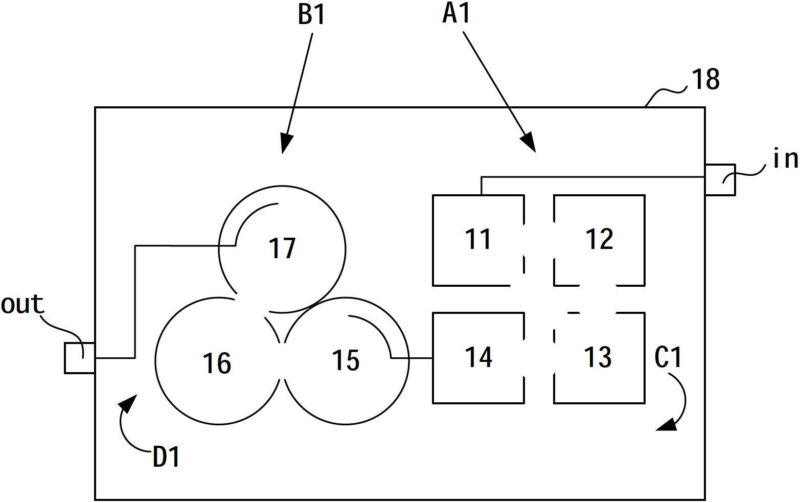
[0020] An embodiment of the present invention provides a filtering device, such as figure 1 As shown, the device includes: a first-level unit and A1 a second-level unit B1.

[0021] The first-stage unit A1 is composed of at least three coaxial filters (11, 12, 13, 14), and the coaxial filters are arranged in sequence, for example, in the order of 11->12->13->14. arranged in order to form the arrangement direction C1. Each of the coaxial filt...


PUM


Abstract

An embodiment of the invention discloses a filtering device, and relates to the technical field of mobile communication. The filtering device solves problems of high insertion loss and poor far-end suppression performance of an existing filter. The filtering device in the embodiment is characterized in that a pass band of a primary unit consisting of at leas three coaxial filters covers a pass band of a secondary unit consisting of at least three dielectric filters, the bandwidth of the primary unit is twice of that of the secondary unit, so that when the coaxial filters are coupled to the dielectric filters, insertion loss of the coaxial filters is reduced, and total insertion loss of the filtering device is lowered. The transmission zero of the primary unit is positioned at second harmonic frequency point of the secondary unit, so that the filtering device has high suppression degree to secondary harmonic waves, and a good far-end suppression performance is realized. The filtering device in the embodiment is mainly used as a duplexer of a transceiver module of a base station.

Description

technical field [0001] The invention relates to the technical field of mobile communication, in particular to a filtering device. Background technique [0002] Filters are widely used in mobile communication systems. For example, the duplexer of the transceiver module of the base station is composed of an RF (Radio Frequency, referred to as: radio frequency) cavity filter, which is located on the back of the transceiver board. On the hardware, it is used for the transmission of single-channel high-power radio frequency signals. Among them, the cavity filter usually adopts a coaxial filter with a coaxial cavity. [0003] With the development of mobile communication technology in the direction of multi-band, coaxial filters are increasingly unable to meet the low insertion loss requirements of mobile communication systems, and the emergence of TE (transverse wave) 01 mode dielectric filters with dielectric cavities solves the problem. this problem. The TE01-mode dielectric ...

Claims


Application Information

Patent Timeline
IPC IPC(8): H01P1/20H01P5/08
CPCH01P1/205H01P1/20H01P1/2136H01P1/2084H01P1/202
Inventor 周彦昭
Owner HUAWEI TECH CO LTD
Why Eureka
Try Eureka