Multilayer growth by gas phase deposition

A gas phase and coating technology, applied in coatings, electrical components, gaseous chemical plating, etc., can solve problems such as hazards and hindering coatings

Inactive Publication Date: 2012-09-26
BRIGHAM YOUNG UNIV
View PDF4 Cites 1 Cited by
  • Summary
  • Abstract
  • Description
  • Claims
  • Application Information

AI Technical Summary

Problems solved by technology

This uncovered substrate crevice may introduce reactivity to the sy...

Method used


Image

  • Multilayer growth by gas phase deposition
  • Multilayer growth by gas phase deposition
  • Multilayer growth by gas phase deposition

Examples


Embodiment 1

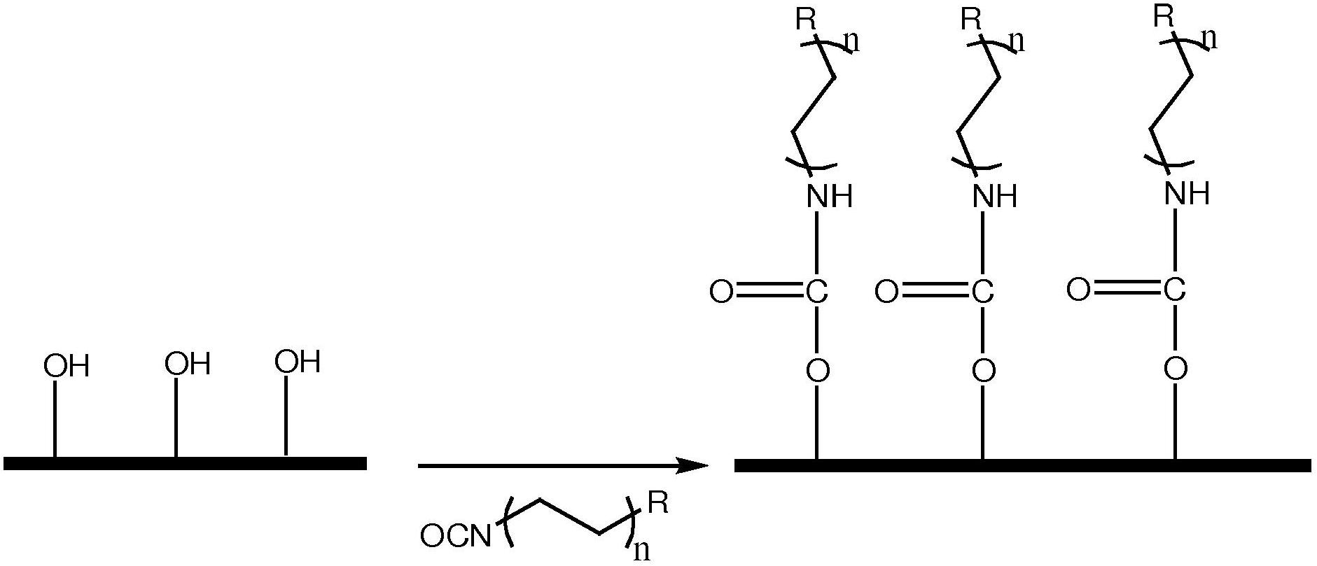
[0041] exist figure 1 An example of application of Chemical A to start application of a multi-layer system is shown in . Substrates with -OH reactive sites react with isocyanates.

[0042] R can be a carbon chain where n is 1 to 30, R is a charged species for cation / anion chromatography, or isocyanate or thioisocyanate.

Embodiment 2

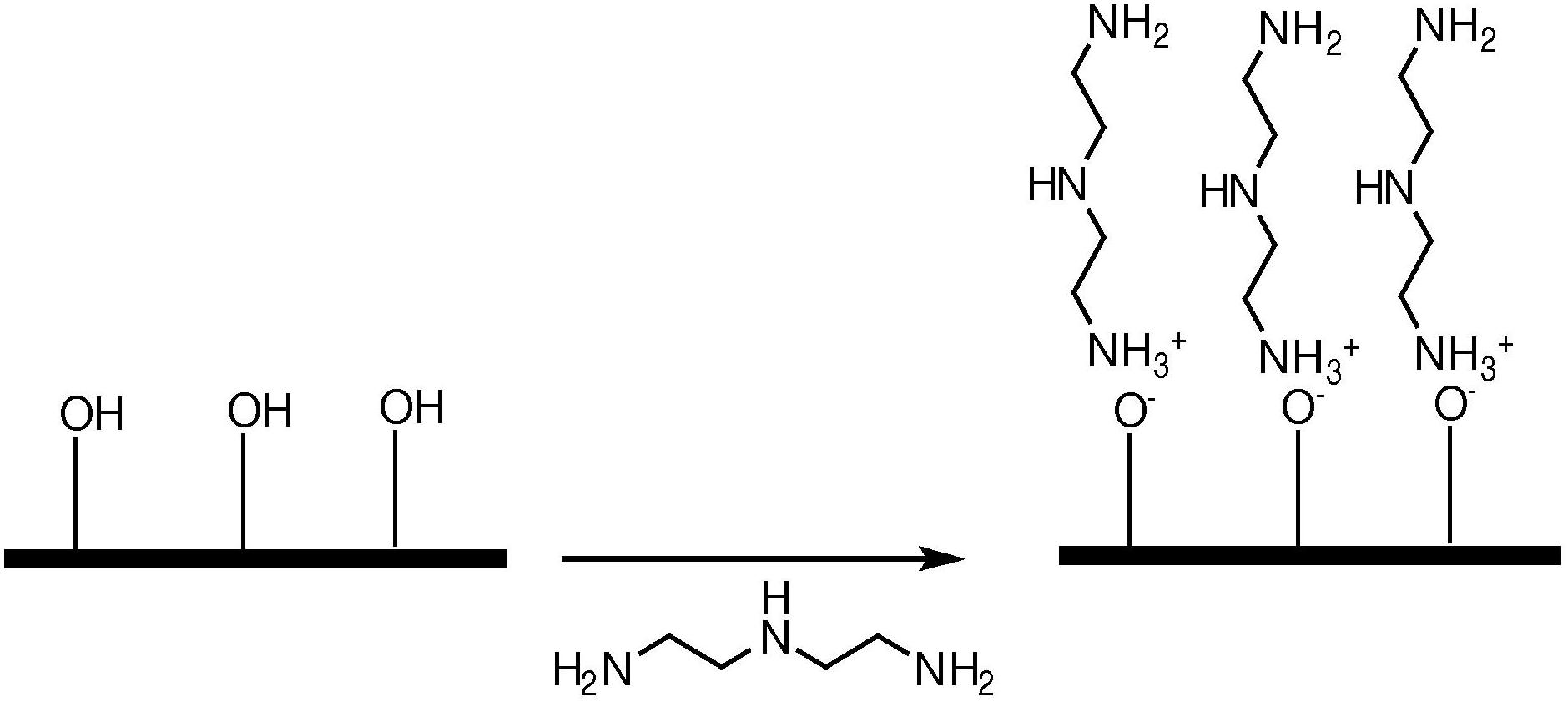
[0044] exist figure 2Another example of applying chemical A to form a multilayer system is shown in , where chemical A is a triamine. Since surface alcohols are acidic, they can form ionic bonds with triamines. In addition, the free amine——NH 2 Functional groups - can react with chemicals such as those with isocyanato groups to create bonded and cross-linked layers.

Embodiment 3

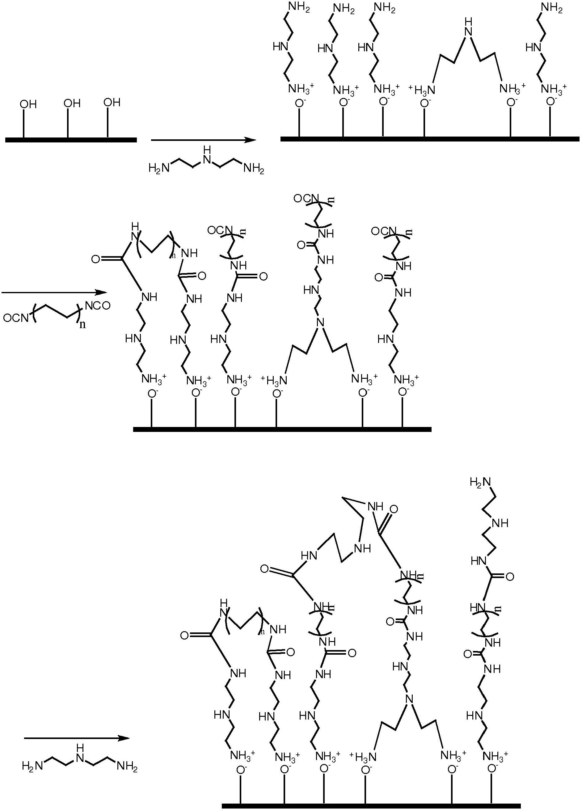
[0046] An amino terminated monolayer as in Example 2 can be reacted with Chemical B, an isocyanate, to produce a crosslinked material that will be stable under acidic conditions. Apply a monolayer and react like Figure 3A shown. The AB multilayer is then reacted with a triamine (same as chemical A), which is then reacted with chemical C with terminal reactive groups, as in Figure 3B shown.

[0047] The multilayer system can be characterized as ABCD, where C=A, where A=triamine, B=diisocyanate, D=monoisocyanate or monoepoxide with an alkyl chain length of 2-30 carbon units. This method produces highly crosslinked stationary phases, which can be attributed to diisocyanates or triamines. In addition, A and B layers can be similarly applied to form AB) n CD or (AB) n C multi-layer system, wherein n is 2 or more.


PUM


Abstract

A multilayer system where intermediate well bonded and cross-linked layers provide attachment for a finishing layer with desired reactive sites.

Description

[0001] Cross References to Related Applications [0002] Priority is claimed to US Provisional Patent Application No. 61 / 280,866, filed November 10, 2009, which is incorporated by reference. Background technique [0003] Substrates used in a variety of applications are coated to provide desired surface properties. There is a continuing need for methods of applying such coatings that provide a strong bond to the coating and the ability to modify the reactive or non-reactive nature of the surface. A problem that can occur in existing coatings such as those used in chromatography is the failure of the bond between the coating and the substrate. Many of these coating systems use strong covalent and ionic bonds, but under the conditions of use, even small amounts of bonding can fail, resulting in crevices in the coating that expose the substrate surface. This can be exacerbated if unbonded coating chemicals have any solubility in the system. This uncovered substrate crevice can ...

Claims


Application Information

Patent Timeline
IPC IPC(8): C23C16/44C23C16/18C23C16/52H01L21/205
CPCB05D7/56B01J20/281C23C16/45525C23C16/30B01J20/3251B01J20/3289B01J20/3221B01J20/3217B01J20/286B05D1/60Y10T428/31511Y10T428/31551
Inventor M·R·林福德D·S·詹森F·张
Owner BRIGHAM YOUNG UNIV
Why Eureka
Try Eureka