Orbital implant coating having bulbously raised suture zone

a suture zone and implant technology, applied in the field of orbital implants, can solve the problems of difficult insertion and general unwanted condition of implant exposure, and achieve the effects of reducing irritation to neighboring tissues, facilitating rapid fibrovascular ingrowth, and facilitating insertion

Inactive Publication Date: 2012-02-21
PERRY ARTHUR C
View PDF10 Cites 12 Cited by
  • Summary
  • Abstract
  • Description
  • Claims
  • Application Information

AI Technical Summary

Benefits of technology

[0012]These and other objects are achieved by an orbital implant having a smooth, bioabsorbable coating at least partially covering a porous core. This provides a smooth surface for easy insertion and reduced irritation to neighboring tissues. In one embodiment, the coating is made to have a portion which is adapted to be bioabsorbed more rapidly than other portions, thereby encouraging rapid fibrovascular ingrowth. Another portion can be adapted to be bioabsorbed less rapidly than other portions, thereby encouraging epithelial cell growth. Optional preformed apertures through the coating enhance fluid flow to and from the core, expose the core to attached muscles, and facilitate suturing. In an alternate embodiment, a deviation of the coating from the nominal shape of the porous core may further facilitate attachment of the muscles by the creation of a clearance between the muscle attachment windows and the suture access openings. An indicia or visual indicator may be associated with the coating to facilitate proper orientation during implantation. Coating materials are selected to determine bioabsorbtion rates, to secure therapeutic agents thereon, to provide stable, secure attachment of extraocular muscles, and to provide adequately strong securing of the coating to the porous core, to allow for sterile packaging, and to provide an adequate shelf life.

Problems solved by technology

Naturally derived HA exhibits surface spicules which can abrasively contact other structures within the orbit which can make insertion difficult.
Further abrasion can occur after insertion, leading to the generally unwanted condition of exposure of the implant.
Unfortunately, such a coating can discourage rapid fibrovascular ingrowth by blocking access of bodily fluids and blood vessels to the porous core.

Method used


Image

  • Orbital implant coating having bulbously raised suture zone
  • Orbital implant coating having bulbously raised suture zone
  • Orbital implant coating having bulbously raised suture zone

Examples


example

[0057]Enucleation: A standard enucleation is done including tagging of the extraocular muscles with bioabsorbable suture. The orbit is sized, using a set of sizing spheres, to determine the size of the implant to be used. An implant is of the proper size when it is the largest implant that can be placed deep into the orbit without creating tension on the overlying tissues and while allowing adequate room for an artificial eye of sufficient thickness.

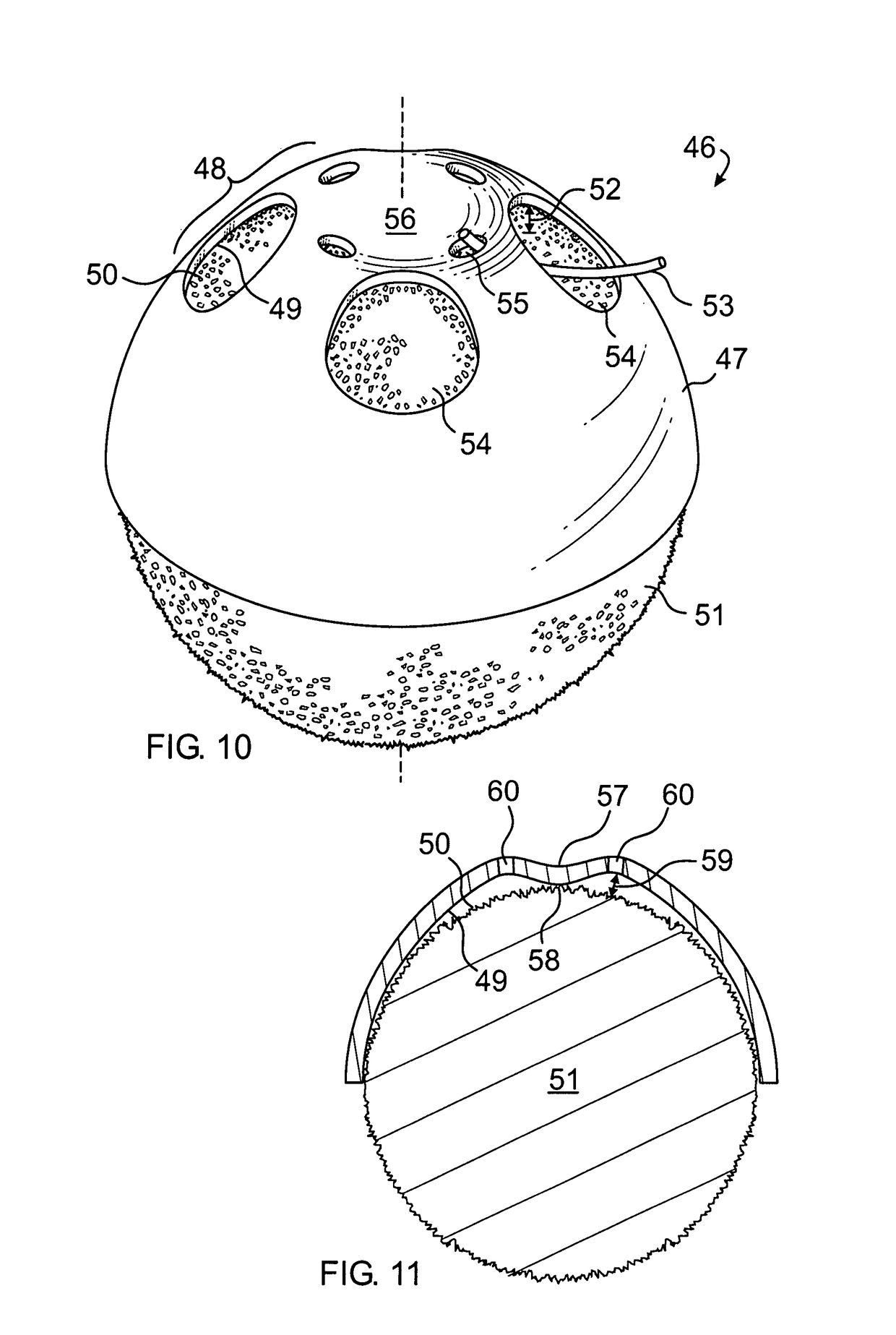
[0058]Once the desired size of the implant has been determined, a sterile marking pen is used to draw the location of the muscle windows on the anterior polymer. The muscle windows are most easily cut by using a fine tipped, high temperature (>1093° C. or >2000° F.) battery operated handheld cautery and by cutting the coating material along the previously drawn lines. The remaining small pieces of polymer inside the windows can then be removed with forceps. In a similar manner suture exit holes may be formed in proximity to the windows. ...


PUM


Abstract

A coating for an orbital implant where the coating has an anterior portion having a different, longer term bioabsorbability than a posterior portion. This allows the implant to have a smooth surface for insertion and to provide reduced irritation to neighboring tissues, to help prevent exposure of the porous core of the implant, and to provide a stable anchorment for extraocular muscles, but which also encourages rapid fibrovascular ingrowth. The coating is marked with a visual indicator to facilitate proper orientation. Shell materials are further selected to allow for sterile packaging, the securing of therapeutic agents thereon, and to provide adequately strong securing of the coating to the core. Apertures are formed through the coating to enhance fluid flow to and from the core, and to provide exposure of the surface of the core to extraocular muscles, and for sutures. The apertures are sized and shaped to reduce irritating surface contact with orbital tissues. In an alternate embodiment, one of the coating portions has a bulbous raised zone encompassing suture holes. The gap created between the undersurface of the raised zone and the core facilitates threading of the sutures.

Description

PRIOR APPLICATION[0001]This application is a continuation-in-part of U.S. patent application Ser. No. 10 / 728,066 field Dec. 3, 2003 now U.S. Pat. No. 7,407,510.FIELD OF THE INVENTION[0002]This invention relates to orbital implants for reconstructive surgery of the socket and orbit and more particularly to materials and methods for enhancing fibrovascular ingrowth and full integration of orbital implants.BACKGROUND OF THE INVENTION[0003]Enucleation or evisceration of the eye is performed because of disease or trauma that make the removal of the eye, or the intraocular contents of the eye, necessary. Following such a procedure, the patient normally desires use of an artificial eye to restore a more normal appearance. To satisfactorily fit an artificial eye into the orbital socket, an orbital (herein also called an “ocular”) implant must be placed within the orbit to replace the volume that was lost when the eye or its contents was removed. However, the use of an orbital implant and th...

Claims


Application Information

Patent Timeline
Patent Type & Authority Patents(United States)
IPC IPC(8): A61F2/14A61F2/00
CPCA61F2/141A61F2/0077A61F2250/003A61F2250/0067A61F2250/0097
Inventor PERRY, ARTHUR C.GREENWALD, ROGER J.
Owner PERRY ARTHUR C
Why Eureka
Try Eureka