Life-saving descent control device

A slow-down and set-up technology, applied in life-saving equipment, building rescue, etc., can solve the problems of weight and volume not being too large, endangering the life safety of users, and fast descending speed of the life-saving slow-down device

Inactive Publication Date: 2012-10-03
刁治亨
View PDF6 Cites 2 Cited by
  • Summary
  • Abstract
  • Description
  • Claims
  • Application Information

AI Technical Summary

Problems solved by technology

Since the life-saving slow-descent device is a life-saving device for personal use, it is required that its weight and volume should not be too large. During the process of sliding down from the window or roof of a high-rise building, the descending speed should be reasonable a

Method used


Image

  • Life-saving descent control device
  • Life-saving descent control device
  • Life-saving descent control device

Examples


Embodiment Construction

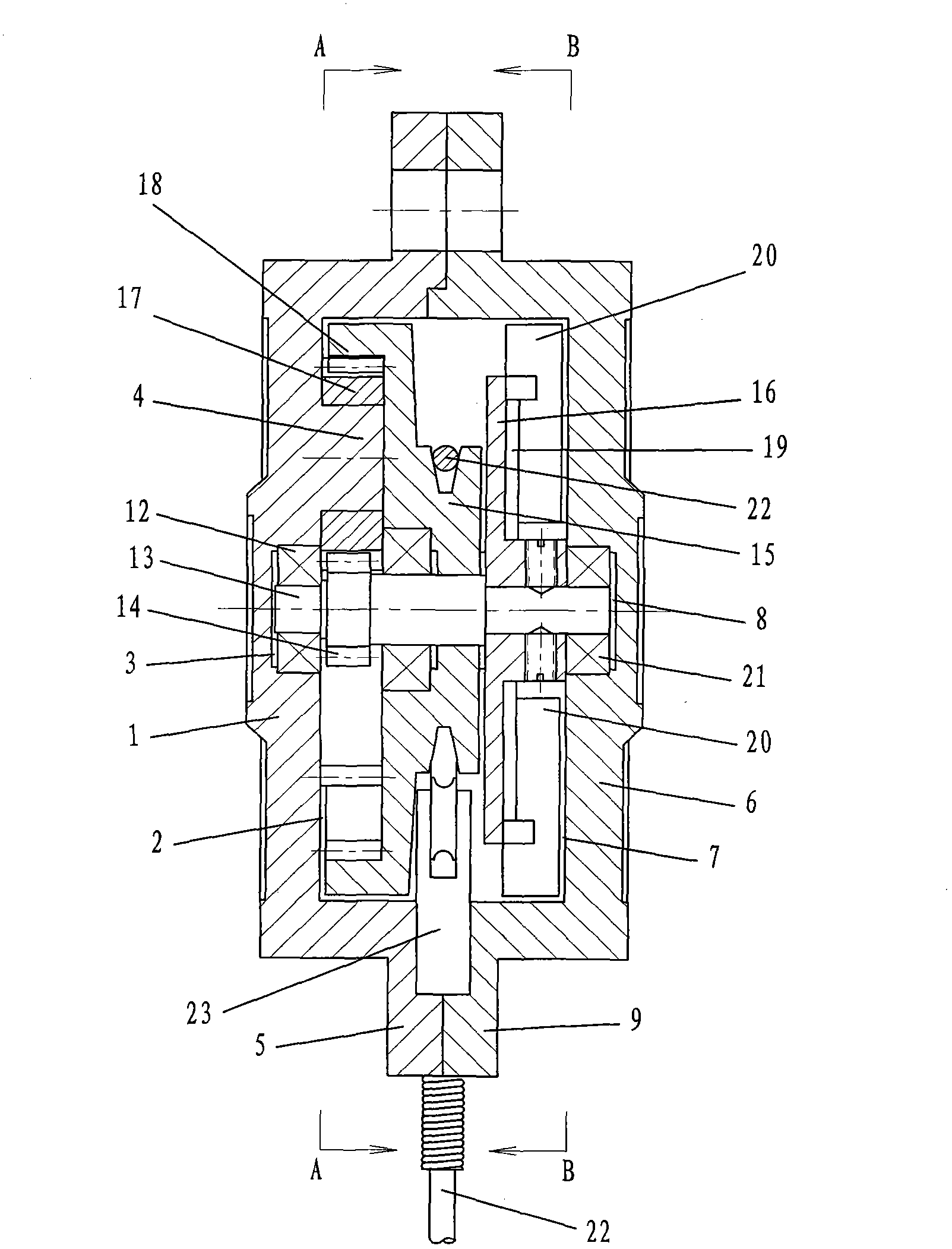
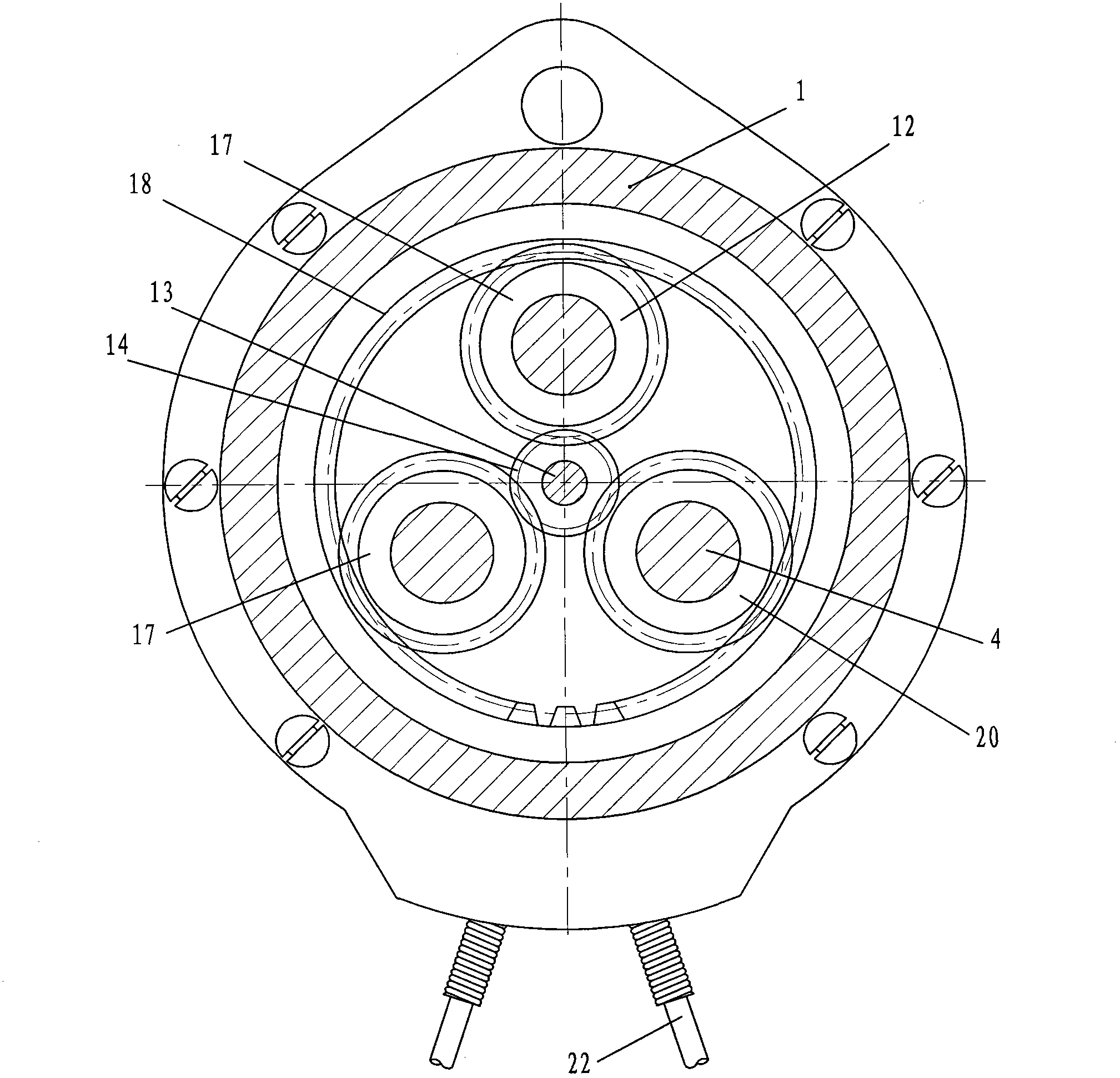
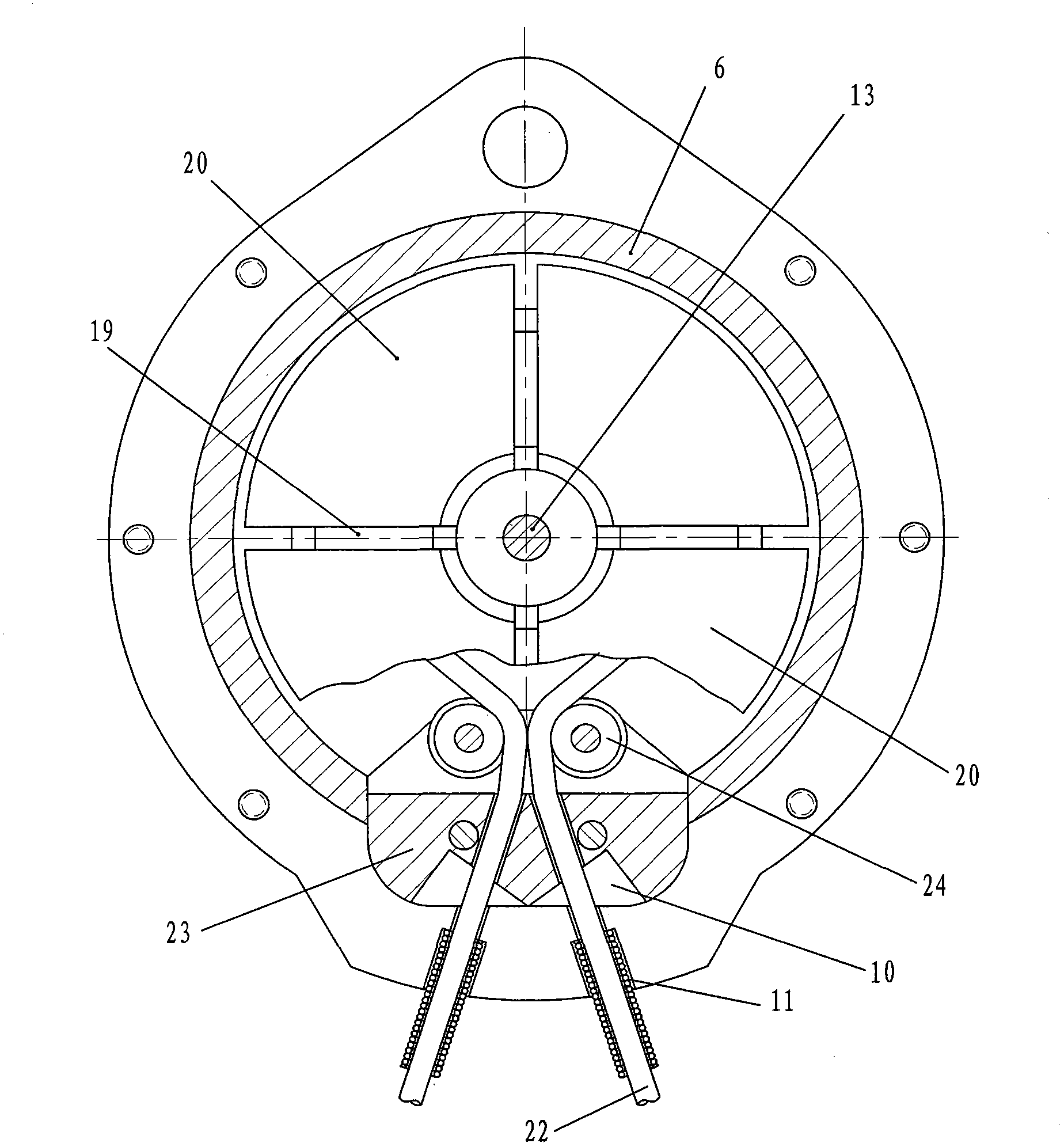
[0014] Depend on figure 1 , figure 2 and image 3 It can be seen that the lifesaving slow descent device of the present invention comprises a left housing 1 and a right housing 6, the right end surface of the left housing 1 is provided with a disc-shaped left circular cavity 2, and the center of the left circular cavity 2 The axis is located in the left and right horizontal direction. The left housing 1 is located at the center of the left circular cavity 2 and is provided with a left counterbore 3 for installing bearings. The central axis of the left counterbore 3 coincides with the central axis of the left circular cavity 2. There are three planetary gear installation shafts 4 inside the circular cavity 2, the axes of the three planetary gear installation shafts 4 are located in the left and right horizontal directions, and the axes of the three planetary gear installation shafts 4 are equidistant and symmetrically distributed around the center of the left circular cavity ...


PUM

PropertyMeasurementUnit
Diameteraaaaaaaaaa
Diameteraaaaaaaaaa
Depthaaaaaaaaaa

Abstract

The invention discloses a life-saving descent control device, which comprises a left shell and a right shell, wherein the right end face of the left shell is provided with a disc-shaped left circular cavity; a left counter bore used for installing a bearing is at the central position of the left shell, which is located on the left circular cavity; three planetary gear mounting shafts are arranged in the left circular cavity; the left ends of the three planetary gear mounting shafts are connected with the left shell into a whole; the outer edge of the right end of the left shell is provided with a left flange; the left end face of the right shell is provided with a disc-shaped right circular cavity; a right counter bore used for installing the bearing is arranged at the central position of the right shell, which is located on the right circular cavity; the outer edge of the right end of the right shell is provided with a right flange; the left end face of the right flange and the right end face of the left flange are pasted; a placement cavity is arranged between the right flange and the left flange; and the placement cavity is communicated with the outside through two steel wire rope perforations. The invention aims to provide the life-saving descent control device which is small in size, high in strength and safe and reliable in performance.

Description

technical field [0001] The invention relates to a lifesaving slow descent device. Background technique [0002] The life-saving slow-descent device is a device that allows people to directly drop from the window or roof of a high-rise building in the event of a fire or other disasters. Patent No. 201120100458.6, the invention patent of the invention name "reciprocating life-saving slow-down device", discloses such a life-saving slow-down device. Since the life-saving slow-descent device is a life-saving device for personal use, it is required that its weight and volume should not be too large. During the process of sliding down from the window or roof of a high-rise building, the descending speed should be reasonable and even, which involves multiple components. If the design of its structural size is unreasonable, it will often cause the descending speed of the life-saving slow-descent device to be either too fast or too slow, and even endanger the life safety of the user ...

Claims


Application Information

Patent Timeline
IPC IPC(8): A62B1/10
Inventor 刁治亨于清福
Owner 刁治亨
Why Eureka
Try Eureka