Filtering dust collector

A dust collector and filtering technology, applied in the fields of dispersed particle filtration, chemical instruments and methods, and dispersed particle separation, etc., can solve the problems of reduced working efficiency of dust collectors, easy retention on the surface of the filter screen, and easy dust removal. The effect of enhancing the vibration amplitude and the degree of expansion and contraction, maintaining stability and maintaining work efficiency

Inactive Publication Date: 2012-10-03
鄂尔多斯市中誉能源股份有限公司
View PDF4 Cites 3 Cited by
  • Summary
  • Abstract
  • Description
  • Claims
  • Application Information

AI Technical Summary

Problems solved by technology

[0005] The technical problem to be solved by the present invention is that in the prior art, the position of the filter screen surface close to the filter net cover and the filter screen support generates vibration and deformation to a greater extent, while the position far away from the filter net cover and filter screen support produces vibration and deformation. The degree is very small, so the dust on the surface of the filter screen close to the position of the filter net cover and the filter net bracket is easily shaken off, while the surface of the filter net far away from the position of the filter net cover and the filter net bracket is easy to retain dust, so with the use time The extension of these positions, due to the accumulation of too much dust, the gas cannot pass through, resulting in the reduction of the working efficiency of the dust collector, and even the inability to work; then a filter type dust collector that can remove the retained dust at various positions on the surface of the filter screen in time is proposed

Method used


Image

  • Filtering dust collector
  • Filtering dust collector
  • Filtering dust collector

Examples


Embodiment Construction

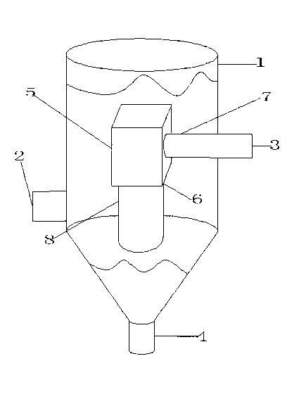
[0032] The structure of filter type dust remover of the present invention is as figure 1 As shown, it includes a housing 1, the upper part of the housing 1 is provided with an air outlet 3, and the lower part of the housing 1 is provided with an air inlet 2, wherein the air outlet 3 and the air inlet 2 can be arranged according to the situation On the side wall on the same side of the housing 1 or on the opposite side wall centered on the axis of the housing 1 , in this embodiment, the air outlet 3 and the air inlet 2 are arranged on the side of the housing 1 On the opposite side wall with the axis as the center; the bottom of the housing 1 is provided with a dust outlet 4, and the dust outlet 4 can be arranged at any position on the bottom of the housing 1 according to the situation. In this embodiment Among them, the dust outlet 4 can be controlled to open and close and is arranged directly below the filter component 8 . A fan 5 and a filter member 8 are fixedly arranged in...


PUM


Abstract

The invention relates to a filtering dust collector which comprises a shell. The upper part of the shell is provided with a smoke outlet, the lower part is provided with a smoke inlet, and the bottom is provided with a dust discharge hole; a fan and filtering components are fixedly arranged in the shell; the air outlet of the fan is communicated with the smoke outlet; the filtering components comprise a spring and a filtering bag; the filtering bag wraps the outer surface of the spring and at least contacts a part of a spring ring; one end of the filtering bag is sealed; the unsealed end of the filtering bag is communicated with the air inlet of the fan; two ends of the spring penetrate through the unsealed end of the filtering bag and the air outlet of the fan in sequence through an extension rod and are connected with the inner wall of the fan; a vibrator is connected with the spring; a separating plate which is connected with the inner wall of the fan is axially arranged in the shell and is perpendicular to the shell; the separating plate separates the fan from the filtering components in a sealing way; a wind shielding plate is fixedly arranged in the shell; and the smoke inlet is provide with a drying component. The filtering dust collector is used for purifying the smoke containing dust.

Description

technical field [0001] The invention relates to a filter type dust collector, which belongs to the field of flue gas treatment. Background technique [0002] The working principle of the filter dust collector is to make the dusty gas pass through the porous filter material. The filter material allows the gas to pass through, but it can intercept the dust in the gas, thereby purifying the dusty gas. Filter dust collectors are widely used in the purification, reuse or discharge of dusty flue gas, such as pharmaceutical, chemical, power generation, cement and other industries. The porous filter material used in the filter dust collector is usually a filter screen composed of fiber fabrics, and the surface of the filter screen can play a role in collecting dust. However, there are also the following problems in the use of filter dust collectors. Because a lot of dust in the flue gas is sticky and adsorbable, this kind of dust is easy to stick to the surface of the filter screen...

Claims


Application Information

Patent Timeline
Patent Type & Authority Applications(China)
IPC IPC(8): B01D46/04
Inventor 王增耀佟秀丽
Owner 鄂尔多斯市中誉能源股份有限公司
Why Eureka
Try Eureka