

Microfluidic reactor
A technology of microfluidic reactors and reaction pools, applied in chemical instruments and methods, chemical/physical/physicochemical processes, chemical/physical processes, etc., can solve problems such as reaction pools that cannot meet requirements, and achieve wide applicability, assembly Simple, even force level effect
- Summary
- Abstract
- Description
- Claims
- Application Information
AI Technical Summary
Problems solved by technology
Method used
Image

Examples
Embodiment 1
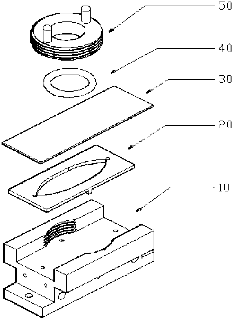
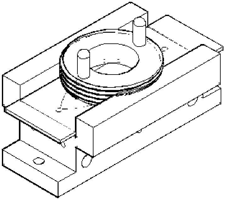
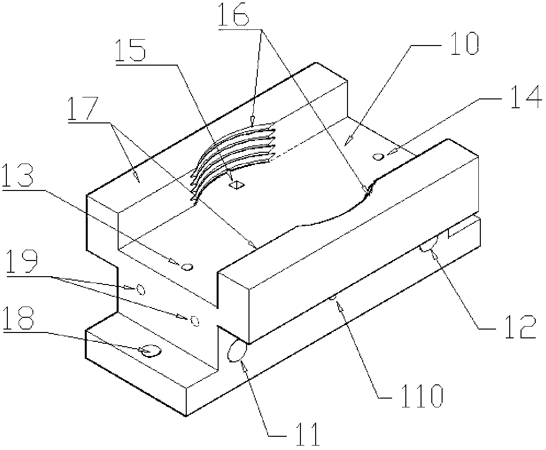
[0037] See attached Picture 1-1 0, a microfluidic reactor comprising: a base 10, a reaction pool plate 20, a slide 30, a rubber ring 40 and a screw cover 50, the reaction pool plate 20 is placed on the base 10, and the slide 30 The cover is on the reaction pool plate 20 , the three constitute a complete reaction chamber, and the rubber ring 40 is buffered and the screw cover 50 is horizontally pressed against the glass slide to seal the reaction chamber.
[0038]The upper and lower surfaces of the reaction pool plate 20 manufactured by using PDMS through grinding tools are flat and smooth, with a length of 60 mm, a width of 25 mm, and a thickness of 1 mm. No bottom, no cover, symmetrical shape, wide in the middle, narrow at both ends, similar to fusiform. Two ends of the reaction pool 24 are circular ports, one is a liquid inlet hole 22, and the other end is a liquid outlet hole 23, both of which have a radius of 0.9mm. The center of the shape of the reaction pool is symmet...
Embodiment 2
[0048] The structure of embodiment 2 is identical with embodiment 1, and concrete structural parameter is:
[0049] ∠ABC, ∠A′B′C′, ∠BAD, ∠B′A′D′ are 135 degrees. The straight line AB and the straight line A'B' are 2 mm long, and the distance between the straight line AB and the straight line A'B' is 2 mm. The width CC' and DD' of the liquid inlet or outlet of the reaction pool are 0.2 mm, and the length of the rectangular channel is 0.3 mm. The total area T of the reaction pool is about 7mm 2 . Fluent simulation is carried out with the inlet velocity 5mm / s, and the uniform area A obtained with the average velocity between 0.46-0.92mm / s is 5.4mm 2 , the uniformity rate R (A / T) is 77.14%; compared with the corresponding conventional diamond-shaped pool, the total area T of the reaction pool is 6.1mm 2 , the uniform area A is 4mm 2 , The uniform rate R is 65.57%. In this embodiment, the uniformity rate of the shuttle-shaped reaction cell is relatively large, indicating that...
Embodiment 3
[0051] The structure of embodiment 3 is identical with embodiment 1, and concrete structural parameter is:
[0052] ∠ABC, ∠A′B′C′, ∠BAD, ∠B′A′D′ are 165 degrees. The length of the straight line AB and the straight line A'B' is 60mm, the distance between the straight line AB and the straight line A'B' is 50mm, the width CC' and DD' of the liquid inlet or outlet of the reaction pool are 6mm, and the length of the rectangular channel is 9mm. The total area T of the reaction pool is about 8979mm 2 . Fluent simulation is carried out at the entrance speed of 50mm / s, and the uniform area A with the average speed between 7.2-10.9mm / s is 6079mm 2 , the uniformity rate R (A / T) is 67.70%; compared with the corresponding conventional diamond-shaped pool, the total area T of the reaction pool is 7706mm 2 , the uniform area A is 4210mm 2 , The uniform rate R is 54.63%. In this embodiment, the uniformity rate of the shuttle-shaped reaction cell is relatively large, indicating that the ...
PUM
 Abstract
Description
Claims
Application Information