
Mould for forging shaft coupling

A technology of couplings and molds, applied in the direction of manufacturing tools, forging/pressing/hammer devices, forging/pressing/hammering machinery, etc., can solve the problems of increasing difficulty, increasing difficulty of operation, waste of raw materials, etc., to improve the quality of materials Utilization rate, reduction of forging time, and improvement of work efficiency

Active Publication Date: 2014-11-12
ZHANGJIAGANG CITY GUANGDA MACHINERY FORGING
View PDF8 Cites 0 Cited by
  • Summary
  • Abstract
  • Description
  • Claims
  • Application Information

AI Technical Summary

Problems solved by technology

Since the coupling is a special-shaped product and requires continuous forging fibers, this requirement is difficult to achieve in free forging, and it is difficult to guarantee the mechanical properties of the product.
In addition, in the process of free forging, stamping is a necessary process in forging. The main reason is that the interval after stamping is short and the wide anvil cannot be pressed, so the upper and lower pads can only be used to elongate. Because the upper and lower pads are very easy to hurt people when turning, other There are safety hazards in the operation; the difficulty of operation is correspondingly increased, the forging time is long, the machining allowance is large, and the material utilization rate is low, so not only waste raw materials but also increase the difficulty of machining

Method used


Image

  • Mould for forging shaft coupling
  • Mould for forging shaft coupling
  • Mould for forging shaft coupling

Examples


Embodiment Construction

[0014] The mold for forging a shaft coupling of the present invention will be further described in detail through specific examples below.

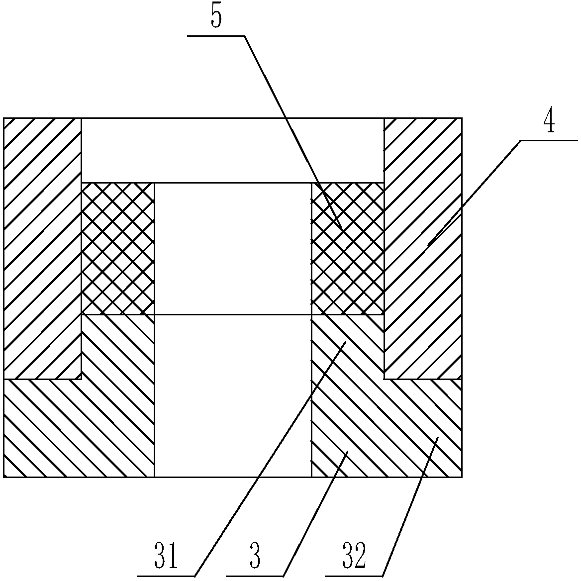
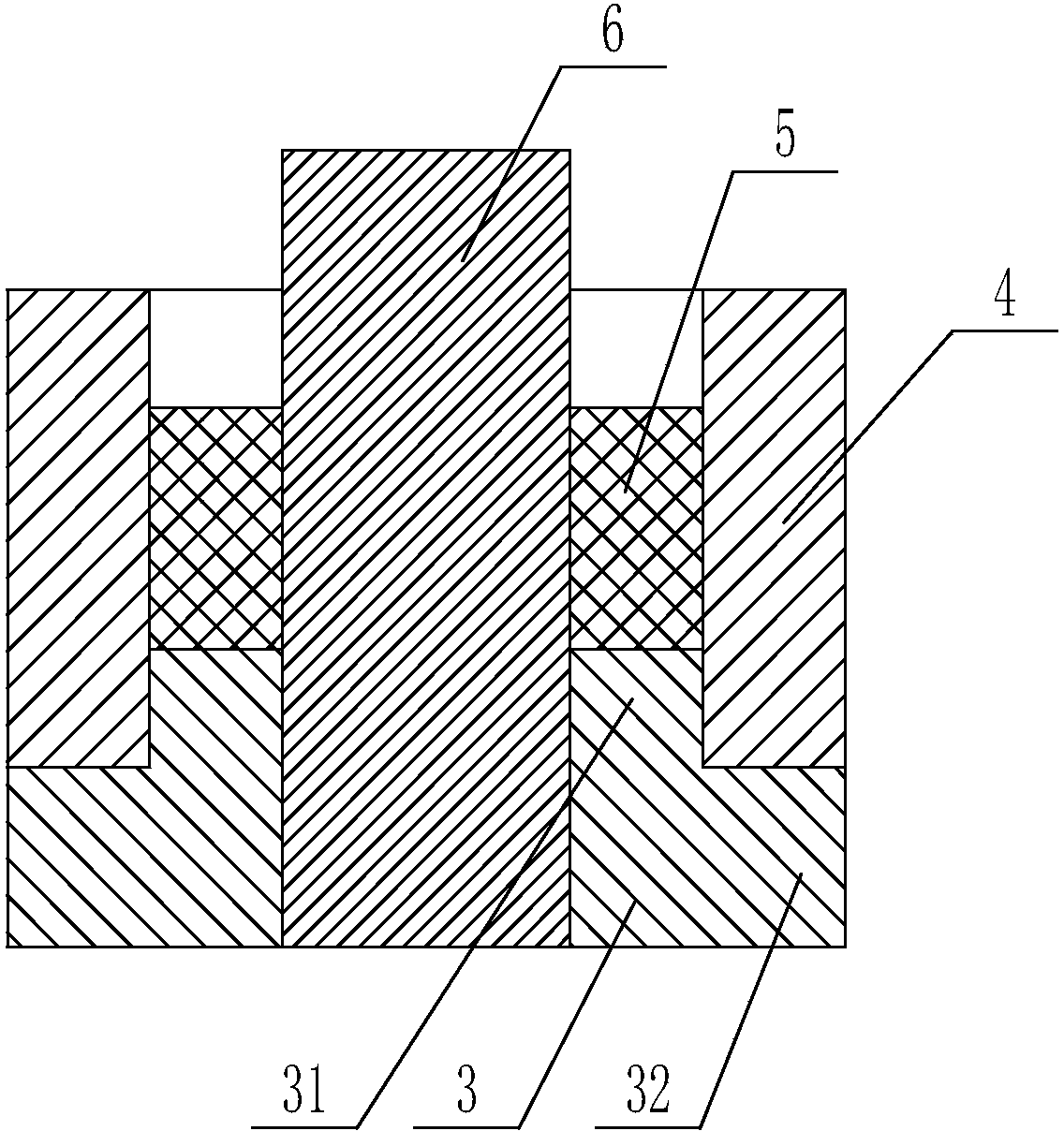
[0015] Such as figure 2 As shown, the mold for forging the coupling includes a lower mold 3, an outer mold 4 and an inner mold 5. The lower mold 3 includes a small ring body 31 and a large ring body 32 arranged concentrically from top to bottom, The external diameter of large torus 32 is greater than the external diameter of small torus 31, and the internal diameter of large torus 32 is equal to the internal diameter of small torus 31, and described outer mold 4 is a torus, and the outer mold 4 Outer diameter equals the outer diameter of big torus 32, and the inner diameter of outer mold 4 equals the outer diameter of little torus 31, and described internal mold 5 is a torus, and the outer diameter of inner mold 5 is equal to little torus 31, the inner diameter of the inner mold 5 is equal to the inner diameter of the small torus 31, th...


PUM


Abstract

The invention relates to a mould for forging a shaft coupling. The mould comprises a lower mould, an outer mould and an inner mould, wherein the lower mould comprises a small circular ring body and a big circular ring body which are arranged in a concentric manner from top to bottom in sequence; the outer diameter of the big circular ring body is smaller than that of the small circular ring body; the inner diameter of the big circular ring body is smaller than that of the small circular ring body; the outer mould is a circular ring body; the outer diameter of the outer mould is equal to that of the big circular ring body; the inner diameter of the outer mould is equal to the outer diameter of the small circular ring body; the inner mould is a circular ring body; the outer diameter of the inner mould is equal to that of the small circular ring body; the inner diameter of the inner mould is equal to the outer diameter of the small circular ring body; the height of the small circular ring body is equal to that of a big cylinder of the shaft coupling needed to be forged; and the height of the outer mould is equal to the integral height of the shaft coupling needed to be forged. The mould is suitable for forging the shaft coupling.

Description

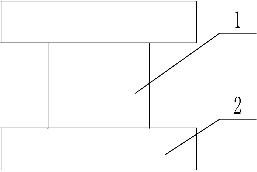
technical field [0001] The invention relates to a die for forging a coupling. Background technique [0002] Coupling, also known as coupling, its structure is as follows figure 1 As shown, it includes a small cylinder 1 in the middle and a large cylinder 2 at both ends of the small cylinder 1, which are mainly used to connect two shafts in different mechanisms so that they rotate together to transmit torque mechanical parts. In the high-speed and heavy-duty power transmission, some couplings also have the functions of buffering, shock absorption and improving the dynamic performance of the shafting. The general power machine is mostly connected with the working unit by means of a coupling. It is an important part of connecting each shaft section of the shaft system. At present, couplings are widely used at home and abroad: such as large machinery, chemical industry, nuclear power plants, ships and other industries. [0003] At present, the main method of producing coupli...

Claims


Application Information

Patent Timeline
Patent Type & Authority Patents(China)
IPC IPC(8): B21J13/02
Inventor 徐卫明杨以振顾金才何云超
Owner ZHANGJIAGANG CITY GUANGDA MACHINERY FORGING
Learn More