
Welding shielding gas device and pipe fitting connecting piece thereof

A technology of shielding gas and connectors, applied in the direction of pipes/pipe joints/fittings, auxiliary devices, welding equipment, etc., can solve problems such as small and difficult installation, welding failure, welding pollution, etc.

Inactive Publication Date: 2012-10-03
HUAHENG WELDING
View PDF6 Cites 8 Cited by
  • Summary
  • Abstract
  • Description
  • Claims
  • Application Information

AI Technical Summary

Problems solved by technology

As a result, the operator may often need to spend a lot of time looking for the corresponding series of compression fittings to achieve the sealing effect, which consumes a lot of material and labor costs
In addition, the compression fittings that need to be found are usually not too large due to the error, so that the impurity gas and the inert gas are introduced together, which does not have the effect of cleaning the inside of the workpiece and affects welding; it is easy to be damaged because it is small and difficult to install.
[0004] Of course, I also thought about using adhesive tape to seal the welding tubular workpiece and clean the gas pipe, but this kind of plan: first, if the sealing performance does not achieve the expected effect, other gases in the atmosphere may be sucked into the clean gas as a protective gas, which will give The welding part brings pollution, which may cause welding failure; in addition, the viscous substance on the adhesive tape will bring volatile compounds and other pollutants into the clean gas flow together after being heated, which will also reduce the quality of the entire welding; more Even, this combination is very unstable and the tensile performance is relatively poor. If the clean air pipe or the well-assembled pipe is suddenly hit, the tape may be easily pulled off, which will affect the internal protection effect.

Method used


Image

  • Welding shielding gas device and pipe fitting connecting piece thereof
  • Welding shielding gas device and pipe fitting connecting piece thereof
  • Welding shielding gas device and pipe fitting connecting piece thereof

Examples


Embodiment Construction

[0029] The present invention will be described in detail below in conjunction with various embodiments shown in the drawings. However, these embodiments do not limit the present invention, and any structural, method, or functional changes made by those skilled in the art according to these embodiments are included in the protection scope of the present invention.

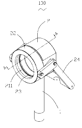
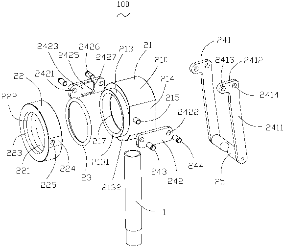
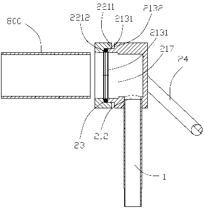
[0030] Please refer to figure 1 Shown is a specific embodiment of the welding shielding gas device 100 of the present invention. Please combine figure 2 and image 3 As shown, the welding shielding gas device 100 includes: a clean gas pipe base (not shown) provided with a clean gas pipe 1 for conveying shielding gas, and a pipe fitting connection fixed at the outlet end of the clean gas pipe 1 to connect a welding pipe 800 piece 2. The pipe connector 2 includes a base 21 connected to the clean air pipe 1, a collar 22 movably positioned at one end of the base 21, a sealing ring 23 embedded between the base 21 an...


PUM


Abstract

The invention provides a welding shielding gas device, which comprises a cleaning gas pipe for conveying shielding gas and a pipe fitting connecting piece fixed at the tail end of the cleaning gas pipe to be connected to a welding pipe fitting, wherein the pipe fitting connecting piece comprises a base connected to the cleaning gas pipe, a lantern ring movably positioned at one end of the base and a sealing ring which is inlayed between the base and the lantern ring and is extruded inwards in the radial direction along the lantern ring to abut against the periphery of the welding pipe fitting when the lantern ring moves along the axial direction of the welding pipe fitting. Therefore, the welding shielding gas device and the welding pipe fitting are connected with each other in a sealing manner, and foreign gas can be prevented from being guided into the welding pipe fitting to influence a welding effect.

Description

technical field [0001] The invention relates to the field of welding technology, in particular to a welding shielding gas device for removing impurity gases in welded pipe fittings and a pipe fitting connecting piece thereof. Background technique [0002] In the welding process, in order to achieve the best weld appearance and weld quality that meets the strength requirements, a welding shielding gas device is generally used to blow shielding gas containing inert gas on the surface of the molten metal to prevent oxidation of the molten metal at the solder joint. However, when it comes to the welding of workpieces with high cleanliness requirements such as electronics, semiconductors, medical treatment and hygienic food, not only the external welds of the workpieces are required to be beautiful, but also the internal welds of the workpieces are required to be beautifully formed without any oxidation, so as to prevent Debris residue from welds. Therefore, in the process of ar...

Claims


Application Information

Patent Timeline
Patent Type & Authority Applications(China)
IPC IPC(8): B23K37/00B23K9/16F16L21/00
Inventor 朱志毅常红坡吴光华侯帅
Owner HUAHENG WELDING
Learn More