Fixed axle assembly in a vehicle, in particular in a vehicle, in particular a commercial vehicle

A commercial vehicle, rigid technology, applied in the direction of vehicle components, axles, wheels, etc., can solve problems such as restrictions on the arrangement of fork links and drive shafts, asymmetry, etc.

Active Publication Date: 2012-10-03
MAN NUTZFAHRZEUGE AG
View PDF7 Cites 2 Cited by
  • Summary
  • Abstract
  • Description
  • Claims
  • Application Information

AI Technical Summary

Problems solved by technology

However, there may be restrictions regarding the structural arrangement of the wishbone and the drive shaft
[0004] A further disadvantage of this construction may be that here

Method used


Image

  • Fixed axle assembly in a vehicle, in particular in a vehicle, in particular a commercial vehicle
  • Fixed axle assembly in a vehicle, in particular in a vehicle, in particular a commercial vehicle

Examples


Embodiment Construction

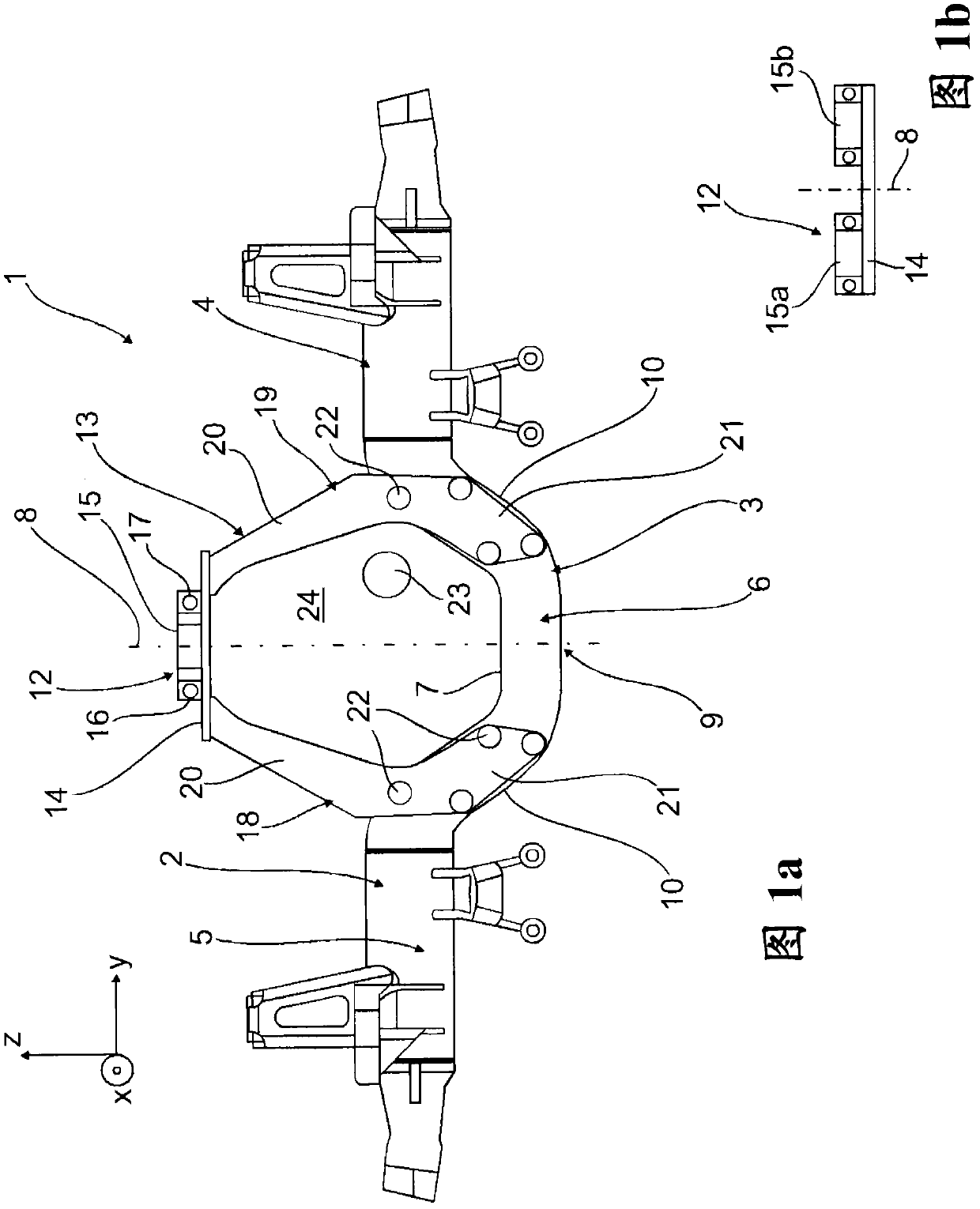
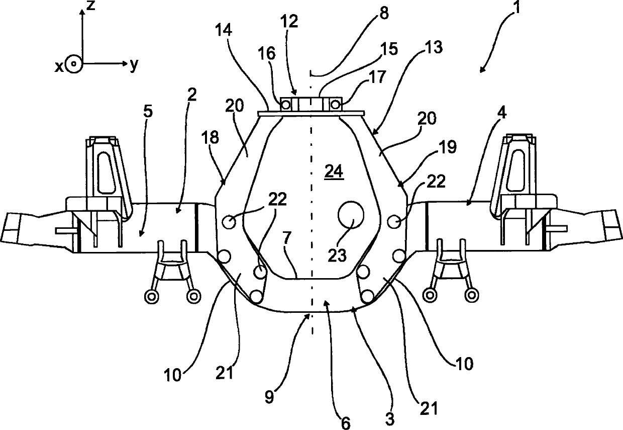
[0050] Figure 1a Shown is a rigid bridge 1 with a combined pontic 2 having a pontic middle part 3 and a pontic side part 4 joined, in particular welded or flanged, to the pontic middle part 3 , 5. In this case, the individual bridge components can be constructed according to the concept of DE 103 33 760 A1.

[0051] The bridge body 2 is provided with a raised area 6 in the region of the bridge body center part 3 , wherein the raised area 7 is directed downwards as viewed in the direction z of the vertical vehicle axis.

[0052] as available from Figure 1a As further obtained in , the projecting region 6 of the bridge body center part 3 extends almost horizontally on both sides of the longitudinal center region 9 of the bridge body 2 delimited by the center axis 8 and thus essentially in the direction of the vehicle transverse axis y extend. Bridge body transition regions 10 , 11 extending obliquely or curved with respect to the vehicle vertical axis direction z and the veh...


PUM


Abstract

The rigid axle assembly has a rigid axle (1) protruding from a multi-point link mounting bracket having control arms (18,19) formed above the axle console side multi-point handlebar attachment area of the mounting bracket and directly/indirectly connected to the frame of vehicle. The multi-point link connection portion (12) is arranged relative to the longitudinal center portion (9) of axle housing (2), starting from the controls arms and leading to the axle housing and connected to opposite sides of the longitudinal central region of axle housing.

Description

technical field [0001] The invention relates to a rigid axle assembly in a vehicle, in particular a commercial vehicle, according to the preamble of claim 1 . Background technique [0002] From this type of document DE 103 33 760 A1 is known a rigid axle of a vehicle, in particular as a lift bar front or rear driven axle of a truck or bus. Here, the pontic of the rigid bridge In its central part it protrudes downwards, and in this region the drive shaft leads to the adjacent axle at a distance across the axle body. Furthermore, the bridge body is articulated to the chassis frame of the vehicle via lower side members and upper wishbones and is braced relative to the chassis frame via springs and shock absorbers. The bridge body is modular (gebaut) and consists of three prefabricated parts held together, specifically a forged or cast middle part formed by means of a yoke and two side parts formed by tubular parts (Seitenteil) Together, the side pieces are welded at the end...

Claims


Application Information

Patent Timeline
IPC IPC(8): B60B35/00
CPCB60B2900/321B60G2200/343B60G2200/315B60B2310/305B60B35/06B60B2360/102B60B35/007B60G2200/42B60G9/00B60Y2200/142
Inventor J·格雷辛格W·尤林格T·维特曼恩
Owner MAN NUTZFAHRZEUGE AG
Why Eureka
Try Eureka