Coiling and unreeling machine
A technology of coiling machine and rotating sleeve, which is applied in the direction of coiling strips, thin material processing, transportation and packaging, etc., which can solve the problems of not being able to apply self-locking cylinders/hydraulic cylinders, not being able to expand tightly, and not being able to expand tightly, etc., to achieve Make up for assembly errors, reduce manufacturing costs, and stabilize operation
- Summary
- Abstract
- Description
- Claims
- Application Information
AI Technical Summary
Problems solved by technology
Method used
Image

Examples
Embodiment 1
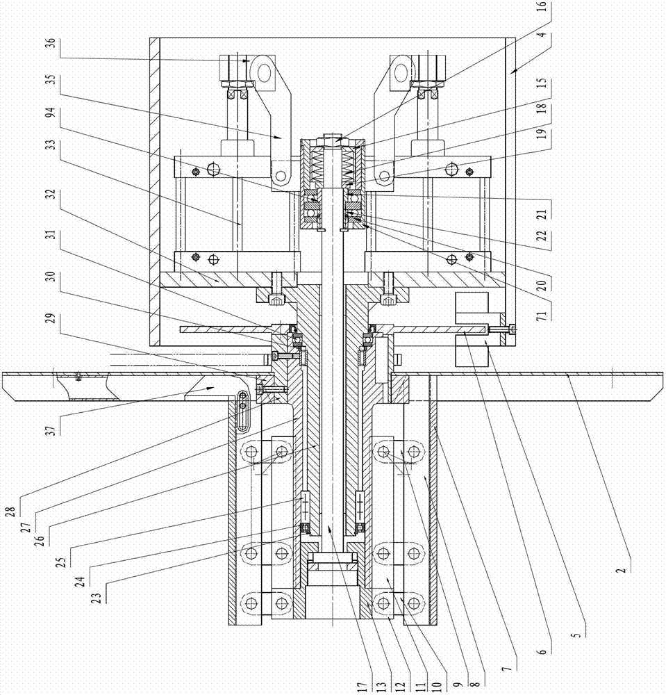
[0076] see figure 1 , a double-sided winding and unwinding machine, comprising a base 1 and a box body rotatably connected to the base 1, the box body includes a bottom plate 4 and two left and right vertical plates 32 affixed thereon, and the outer sides of the two vertical plates 32 are respectively A support sleeve 26 is provided to form a symmetrical double-arm structure. A group of actuators are respectively arranged on the inner sides of the two vertical plates 32 , and each group of actuators drives the pull rods 17 that are arranged on the same side and are installed in the side support sleeves 26 . A powder metallurgy bearing for supporting the pull rod 17 is arranged in the supporting sleeve 26 . The above-mentioned actuator can be a hydraulic cylinder with a lock or an air cylinder with a lock.
[0077] The support sleeve 26 is a sleeve with a flange at one end, wherein the flange part is fastened on the vertical plate 32 of the box body. The support sleeve 26 is...
Embodiment 2
[0115] It is mostly the same as in Embodiment 1, except that the connection mode between the actuator cylinder and the pull rod is changed. In embodiment 1, the retraction of the pull rod is realized by extending the actuator cylinder, and in this embodiment, the retraction of the pull rod is realized by the retraction of the actuator cylinder.
[0116] See Figure 9 , taking the pull rod on the left as an example, the cylinder 33 driving the pull rod 17 is also a group of two, but the difference is that the cylinder rod protrudes toward the left side (the direction close to the outer end of the pull rod connected to it), and each cylinder The end of the cylinder rod is also connected to the end of one arm of the connecting plate 35 through a connecting head 36 . The difference is that the length of the connecting plate in this embodiment is shorter than that in embodiment 1, and the opening direction is different from that in embodiment 1.
[0117] This embodiment also prov...
Embodiment 3
[0120] First structure: see figure 1 with Figure 11a , the tail of each actuator is hinged on the vertical plate of the casing, and the cylinder rod is connected with the sleeve bearing chamber through a lever 35 . The outside of the sleeve bearing chamber is connected with a second ear plate 712 parallel to the axis of the sleeve bearing chamber, and a Y joint 34 is installed on the head of the cylinder rod of the actuator. Hinged, wherein the part hinged with the second ear plate is a long groove rather than a round hole, the middle part of the lever 35 is hinged with the support 63 fixed on the box vertical plate, and the box vertical plate fixed with the support 63 and The driven pull rod 17 is arranged on the same side.
[0121] Second structure: see Figure 11b, forming a second structure in which two actuators 33 of a group are connected with the pull rod: the difference with the above-mentioned first structure is that the afterbody of the actuator 33 is directly in...
PUM
| Property | Measurement | Unit |
|---|---|---|
| Width | aaaaa | aaaaa |
Abstract
Description
Claims
Application Information
 - R&D
- Intellectual Property
- Life Sciences
- Materials
- Tech Scout
- Unparalleled Data Quality
- Higher Quality Content
- 60% Fewer Hallucinations
Browse by: Latest US Patents, China's latest patents, Technical Efficacy Thesaurus, Application Domain, Technology Topic, Popular Technical Reports.
© 2025 PatSnap. All rights reserved.Legal|Privacy policy|Modern Slavery Act Transparency Statement|Sitemap|About US| Contact US: help@patsnap.com