Eureka AIR delivers breakthrough ideas for toughest innovation challenges, trusted by R&D personnel around the world.

Feeding guide rail for cross shearing machine

A cross-cutting machine and guide rail technology, which is used in thin material handling, strip winding, transportation and packaging, etc., can solve the problems of complex structure and poor positioning of feeding guide rails, improve production efficiency, prevent deviation, and improve operation. handy effect

Inactive Publication Date: 2012-10-03
无锡中浦电气有限公司
View PDF5 Cites 11 Cited by
  • Summary
  • Abstract
  • Description
  • Claims
  • Application Information

AI Technical Summary

Problems solved by technology

[0004] The object of the present invention is to provide a feeding guide rail for a cross-shearing machine to solve the problems of complex structure and poor positioning of the feeding guide rail of a traditional cross-shearing machine

Method used


Image

  • Feeding guide rail for cross shearing machine
  • Feeding guide rail for cross shearing machine

Examples


Embodiment Construction

[0015] The technical solutions of the present invention will be further described below in conjunction with the accompanying drawings and through specific implementation methods.

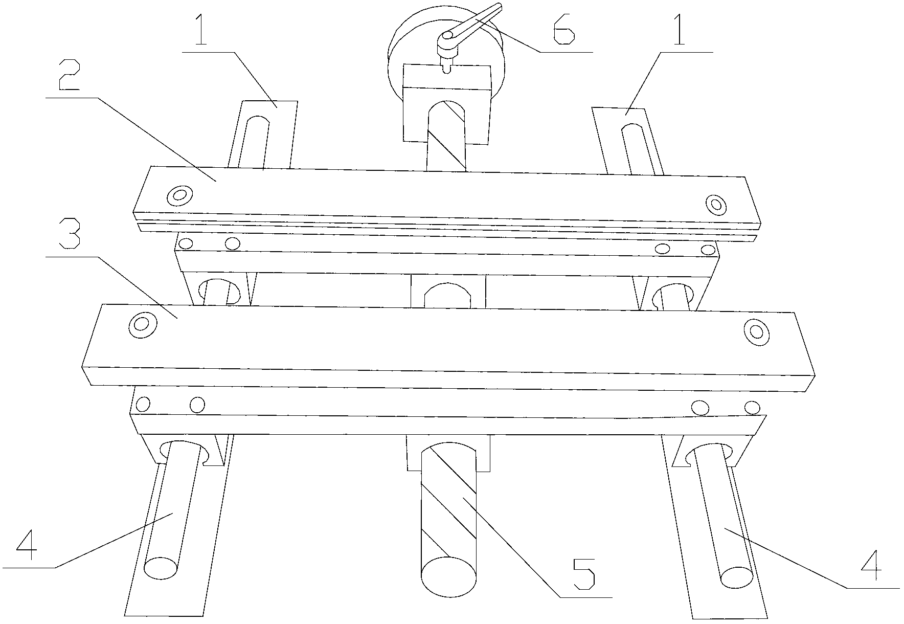
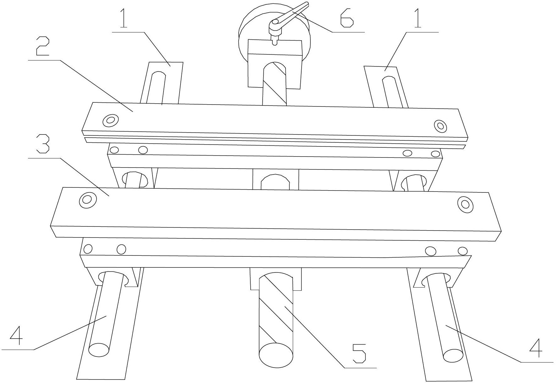
[0016] Please refer to figure 1 as shown, figure 1 It is the structural representation of the feeding guide rail for the cross-shear machine of the present invention;

[0017] In this embodiment, a feeding guide rail for a transverse shearing machine includes a base, on which a bracket 1 and a screw 5 are fixed by bolts, and a shaft 4 is arranged on the bracket 1, and the shaft 4 passes through The sliding blocks arranged at the lower ends of the left guide rail 2 and the right guide rail 3 are slidably connected with the sliding blocks. The inner sides of the left guide rail 2 and the right guide rail 3 are provided with guide wheels, and the lower end of the left guide rail 2 is provided with a nut a. The nut a matches the screw thread at one end of the screw rod 5, and the lower end of the midd...


PUM


Abstract

The invention discloses a feeding guide rail for a cross shearing machine. The feeding guide rail comprises a base, wherein supports and a screw rod are arranged on the base; a left guide rail and a right guide rail are arranged on the support in a slidable manner; a screw nut a is arranged at the lower end in the middle of the left guide rail and is matched with the screw thread at one end of the screw rod; a screw nut b is arranged at the lower end in the middle of the right guide rail and is matched with the screw thread at the other end of the screw rod; and the directions of the screw threads at the two ends of the screw rod are reverse. According to the feeding guide rail for the cross shearing machine, the positions of the left guide rail and the right guide rail are regulated by rotating the screw rod, so as to position a belt and prevent the belt from deflection; and the feeding guide rail has the advantages of simple structure, easiness in implementation, convenience and simplicity in operation and higher production efficiency.

Description

technical field [0001] The invention relates to a feeding guide rail, in particular to a feeding guide rail for a transverse shearing machine. Background technique [0002] Silicon steel sheet is a ferrosilicon soft magnetic alloy with extremely low carbon content. Generally, the silicon content is 0.5% to 4.5%. It is made by hot and cold rolling. The thickness is generally below 1mm, so it is called thin plate. Adding silicon can increase the resistivity and maximum permeability of iron, reduce coercive force, core loss and magnetic aging; silicon steel sheet is mainly used to make iron cores of various transformers, motors and generators. [0003] During the processing of silicon steel sheet, it needs to be cut by transverse shearing machine. However, during the cutting process, especially when feeding by the feeding mechanism, due to the complex structure of the feeding guide rail and poor positioning, the belt material is prone to deviation, resulting in The size of the...

Claims


Application Information

Patent Timeline
Patent Type & Authority Applications(China)
IPC IPC(8): B65H23/032
Inventor 姚胜其
Owner 无锡中浦电气有限公司
Why Eureka
Eureka Blog
Learn More