
Super-large trolley type gas heat treatment furnace

A super-large table and heat treatment furnace technology, which is applied in the direction of furnaces, furnace components, lighting and heating equipment, etc., to achieve the effects of convenient maintenance, avoiding energy waste, and improving energy saving effects

Inactive Publication Date: 2012-10-03
DANYANG JIANGNAN INDAL FURNACE
View PDF6 Cites 30 Cited by
  • Summary
  • Abstract
  • Description
  • Claims
  • Application Information

AI Technical Summary

Problems solved by technology

Although this technical solution can take into account the heat treatment of small workpieces, it still has a fixed furnace volume. When processing super large workpieces or workpieces of different sizes, it is still necessary to dismantle or reassemble the partition wall

Method used


Image

  • Super-large trolley type gas heat treatment furnace
  • Super-large trolley type gas heat treatment furnace
  • Super-large trolley type gas heat treatment furnace

Examples


Embodiment 1

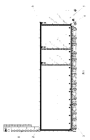
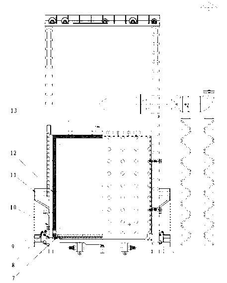
[0028] The overall structure of this embodiment is as figure 1 and figure 2 As shown, the furnace door and the furnace door lifting mechanism 1 are located at the left end of the furnace body. The furnace body is composed of a furnace body steel structure 2 and an inner lining 6. The trolley device 3 can move in the furnace body, and the moving back wall device 5 can move from the furnace body right end. into any position in the furnace body (such as figure 1 The position of the moving back wall depicted by the dotted line in the middle), the moving back wall device 5 realizes the sealing with the furnace body and the trolley device 3 through the rear sealing device 4, and the furnace body realizes the sealing with the trolley device 3 through the side sealing device 7 and the furnace door seal.

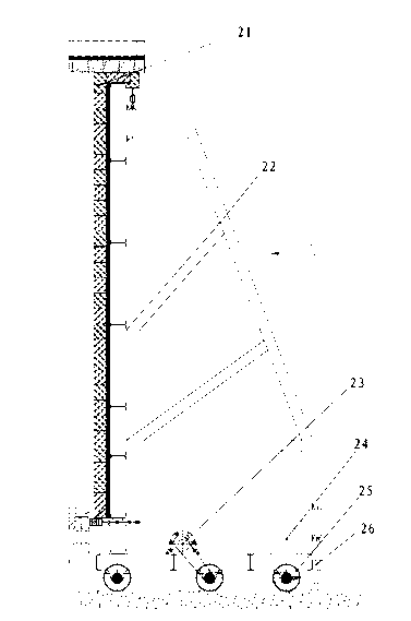
[0029] The structure of the mobile back wall device in this embodiment is as follows: image 3 with Figure 4 As shown, the mobile rear wall device is composed of a rear wall lini...

Embodiment 2

[0034] The structure of this embodiment is basically the same as that of Embodiment 1, and the adjustment steps and sealing process of the moving rear wall are also the same as Embodiment 1. The only difference is that in order to improve the sealing effect at the furnace door, this embodiment is vertically provided with a fire wall on the surface of the trolley. , the position of the fire-retaining wall is set at 10 meters and 20 meters according to user requirements, and the lower edge of the outer side of the fire-retaining wall is laid with 30mm refractory 1260°C fiber. The fire-retaining wall is a seal before the furnace door falls, and the furnace door falls by its own weight It is tight to the refractory fiber on the surface of the trolley to form a secondary seal to achieve a good sealing effect.

Embodiment 3

[0036] In this embodiment, the furnace door anti-falling device is installed on the lifting furnace door of the super-large trolley gas heat treatment furnace on the moving back wall.

[0037] The overall structure of this embodiment is as figure 1 with figure 2 shown. figure 1 It is a cross-sectional schematic diagram of a super large trolley-type gas heat treatment furnace with a moving back wall in this embodiment. This heat treatment furnace changes the fixed back wall of the traditional furnace body into a movable structure, and at the same time ensures that the moving back wall and the top of the furnace body, The reliable sealing between the side walls and the trolley realizes the effective length of multi-section furnace. figure 2 A schematic diagram of the local structure of the lifting furnace door without the anti-fall device is given in this embodiment.

[0038] In this embodiment, an anti-fall device is installed on the left and right sides of the lifting fur...


PUM


Abstract

The invention relates to a super-large trolley type gas heat treatment furnace. The gas heat treatment furnace is characterized in that a fixed rear wall of the conventional furnace body is changed into a movable rear wall, a steel member of the movable rear wall is fixed on a travelling mechanism, and a lining is arranged on the lateral surface of the steel member; and a sealing mechanism is arranged on each of the upper, lower, left and right parts of the movable rear wall, so that the movable rear wall, the lining of the furnace body and a trolley are sealed. Moreover, a furnace door dropping preventing device is added in a furnace door and a lifting mechanism and drives a safety pin by means of a reset force of a spring, once the furnace door drops due to loss of pull, the safety pin quickly extends out, and the furnace door is clamped on upright posts on two sides of the furnace door, so that the furnace door is prevented from continuously dropping. The using efficiency of the super-large heat treatment furnace is effectively improved; energy waste caused by ineffective combustion in the redundant space is avoided; the sealing mechanisms of the movable rear wall are reasonable in structure, easy and convenient to operate and convenient to maintain, and can achieve good sealing performance and increase the overall energy-saving effect of the heat treatment furnace; and thefurnace door dropping preventing device promotes the running safety of the furnace body.

Description

technical field [0001] The invention relates to supporting equipment in the mechanical processing industry, in particular to a super large trolley-type heat treatment furnace with a movable rear wall and a furnace door anti-falling device. Background technique [0002] For large forged workpieces, annealing treatment is required after forging, and then machining is performed. The quality of heat treatment of workpieces plays an important role in machining accuracy and performance of workpieces. For such large forging workpieces, super large heat treatment furnaces are required. However, due to the limited number of super-large workpieces, the utilization rate of super-large heat treatment furnaces whose furnace volume cannot be changed is not high. Waste and waste of energy. [0003] At present, in order to improve the use efficiency of super-large heat treatment furnaces, some technical solutions are: at least one partition wall is arranged on the trolley, and the partiti...

Claims


Application Information

Patent Timeline
Patent Type & Authority Applications(China)
IPC IPC(8): C21D1/00F27D1/00
Inventor 马建国张志平
Owner DANYANG JIANGNAN INDAL FURNACE
Learn More