
Conductive automatic clamping device for electrode of electric slag furnace

An automatic clamping and electroslag furnace technology, which is applied in the field of special metallurgical equipment, can solve the problems of long cooling time and low production efficiency of large electroslag ingots

Active Publication Date: 2013-08-21
SUZHOU ZHENWU ELECTRIC FURNACE +1
View PDF7 Cites 0 Cited by
  • Summary
  • Abstract
  • Description
  • Claims
  • Application Information

AI Technical Summary

Problems solved by technology

The single-station electroslag furnace cannot be produced during the cooling period of the electroslag ingot, and the cooling time of the large ingot type electroslag ingot is longer, and the production efficiency is reduced

Method used


Image

  • Conductive automatic clamping device for electrode of electric slag furnace
  • Conductive automatic clamping device for electrode of electric slag furnace
  • Conductive automatic clamping device for electrode of electric slag furnace

Examples


Embodiment Construction

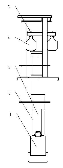
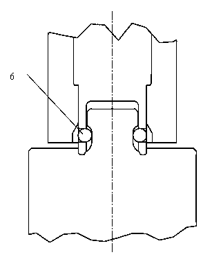
[0011] With reference to the drawings, the structure includes auxiliary electrode 1, conductive material rod 2, fixed shaft 3, film cylinder 4, fixed plate 5, marbles 6; wherein conductive material rod 2 is connected to auxiliary electrode 1 through marbles 6, and the fixed shaft 3 and the fixed plate 5 are fixed on the furnace head support, the conductive material rod 2 is outside the fixed shaft 3, and the conductive material rod 2 is connected with three film cylinders 4 to form an up and down moving sleeve.

[0012] The fixed shaft 3 and the fixed plate 5 form a fixed shaft part, and the fixed shaft 3 and the fixed plate 5 are fixed on the furnace head support.

[0013] The up-and-down moving sleeve is formed by connecting a conductive material rod 2 and three film cylinders 4. Under the power of the film cylinder 4, the conductive material rod 2 moves vertically outside the fixed shaft 3.

[0014] Several marbles 6 take on the role of connecting the conductive material rod 2 and...


PUM


Abstract

The invention provides a conductive automatic clamping device for an electrode of an electric slag furnace. The conductive automatic clamping device is characterized by comprising an auxiliary electrode, a conductive material rod, a fixing shaft, thin film air cylinders, a fixing board and a marble, wherein the conductive material rod is connected to the auxiliary electrode through the marble; the fixing shaft and the fixing board are fixedly arranged on a furnace head bracket; the fixing shaft is arranged on the outer side of the conductive material rod; and a vertical moving sleeve consistsof the conducive material rod and the three thin film air cylinders. The conductive automatic clamping device provided by the invention has the advantages that the device for automatically locking bymeans of using the three thin film air cylinders as power to drive a water cooling inner sleeve material rod to slide a ceramic ball group is designed. The conduction problem, caused by large lockingcontact current (40000 A) of a large-size consumable electrode and the conductive material rod of the 120-t electric slag furnace, can be solved.

Description

technical field [0001] The invention relates to an electroconductive automatic clamping device for electrodes of an electroslag furnace, which belongs to the technical field of special metallurgical equipment. Background technique [0002] A traditional electroslag furnace is generally composed of a support arm, a column, a short net, a transformer, and a trolley supporting the ingot. In the traditional single-column support-arm type and double-column rotating support-arm type double-station electroslag furnace, the support arm clamp clamps the dummy electrode and the metal electrode, and the control transmission device rotates the T-shaped screw to drive the roller cantilever to move up and down to complete the melting. No inert gas shield is provided. Since there is no inert gas protection, it is difficult to control the hydrogenation of electroslag steel, the burning loss of oxygen, nitrogen and easily oxidized elements. Affect the quality of electroslag ingot. The mec...

Claims


Application Information

Patent Timeline
Patent Type & Authority Patents(China)
IPC IPC(8): C22B9/187
Inventor 朱兴发黄森根陈志强高玉龙胡江
Owner SUZHOU ZHENWU ELECTRIC FURNACE
Learn More