
Bottom shaft driven flap gate

A flap gate and driving technology, which is applied in water conservancy projects, sea area projects, coastline protection, etc., can solve problems that affect the safety of project operation, poor water sealing effect, water leakage, etc., and achieve improved water sealing effect and good water sealing effect , to ensure the effect of safety

Active Publication Date: 2015-03-11
SHANDONG SURVEY & DESIGN INST OF WATER CONSERVANCY
View PDF6 Cites 0 Cited by
  • Summary
  • Abstract
  • Description
  • Claims
  • Application Information

AI Technical Summary

Problems solved by technology

The disadvantage is that the water sealing effect of the bottom water seal is poor at the middle bearing of the bottom shaft, and the water leakage phenomenon is serious, and the middle bearing of the bottom shaft is mostly integral, and the cost is high
When maintaining, the whole must be disassembled in the absence of water upstream and downstream, which is extremely inconvenient for maintenance
[0003] Most of the traditional bottom shafts are rigidly connected as a whole. Although the synchronous performance of the bottom shaft transmission is guaranteed, it cannot reasonably release the linear expansion belt due to temperature changes and stress deformation. The coming bottom shaft expands and contracts, resulting in expansion and contraction to both ends, resulting in the sealing effect of the bottom shaft through the wall and the connection between the driving arm and the driving device, which affects the safety of engineering operation in severe cases

Method used


Image

  • Bottom shaft driven flap gate
  • Bottom shaft driven flap gate
  • Bottom shaft driven flap gate

Examples


Embodiment Construction

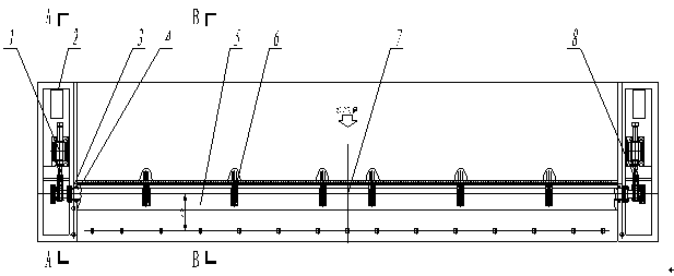
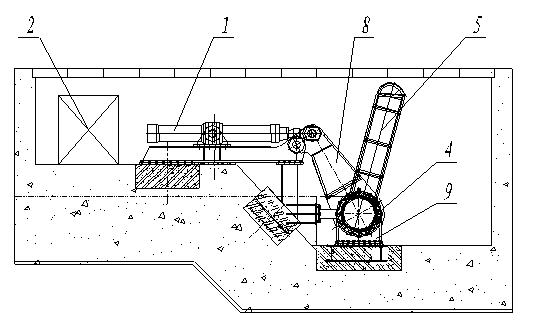
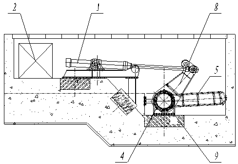
[0023] As shown in the figure, a bottom shaft-driven flap gate includes a driving device 1, a driving arm 8 and a bottom shaft 4 connected to the door leaf 5. The bottom shaft 4 is installed on the bottom shaft intermediate support 6, and the bottom shaft passes through the The connection device 7 is connected, the bottom shaft intermediate support 6 is an open structure, the bottom water seal 10 is in continuous linear contact with the bottom shaft 4; the door leaf 5 is connected with a side water seal, and the side water seal is in contact with the gate wall.

[0024] The bottom shaft intermediate support 6 includes a support base 61, which is an open structure. An open structure composed of two or more sets of bearing groups is arranged on the support base 61. The bearing group is a combination of multiple bearings 66. , the bearing 66 in the bearing group is placed on the support base 61 through the bearing bracket 69, two or more glands 62 are arranged on the left and righ...


PUM


Abstract

The invention discloses a bottom shaft driven flap gate, and aims to provide the bottom shaft driven flap gate capable of improving a water sealing effect at a middle support and eliminating influence of bottom shaft expansion caused by linear expansion due to temperature variation and stress deformation on a pier penetrating water seal and a gate flap. The technical scheme provided by the invention is that the bottom shaft driven flap gate comprises a driving device, a driving arm and a bottom shaft connected with a gate flap, wherein the bottom shaft is arranged on the middle support of the bottom shaft; the bottom shaft is connected in sections through a connecting device; the middle support of the bottom shaft is in an open structure; and the bottom water seal is in continuous linear contact with the bottom shaft. The bottom shaft driven flap gate has the beneficial effects that the middle support is in the open structure; the bottom water seal can be in continuous linear contact with the bottom shaft, the water seal effect of a bottom water stop is greatly improved, the support can be maintained in the working state that water is stopped in front of the gate and no water exists behind the gate, the middle connecting device of the bottom shaft is a synchronous power transmission and gap telescopic connecting device, and the influence of length expansion of the bottom shaft and the gate flap caused by the temperature variation and the stress change on the pier penetrating sealing effect of the bottom shaft and the engineering operation safety is eliminated. The gate has the advantages of simple and compact structure, good water sealing effect, convenience in mounting and maintenance and capability of guaranteeing the engineering operation safety.

Description

technical field [0001] The invention belongs to the field of hydraulic engineering equipment, in particular to a bottom shaft driven flap gate. Background technique [0002] Bottom shaft-driven flap gate is a kind of gate in water conservancy projects. Because of its good landscape effect, it has been used more and more. Most of the traditional bottom shaft intermediate bearing housings are integral bearing housings, and their structure is mostly convex. The bottom water seal is at the bottom shaft intermediate bearing housing, and generally adopts a concave water seal corresponding to the convex circle. The disadvantage is that the water sealing effect of the bottom water seal is poor at the middle bearing of the bottom shaft, and the phenomenon of water leakage is serious, and the middle bearing of the bottom shaft is usually integral, and the cost is relatively high. During maintenance, the whole unit must be disassembled in the absence of water upstream and downstream, ...

Claims


Application Information

Patent Timeline
Patent Type & Authority Patents(China)
IPC IPC(8): E02B7/40E02B7/54
Inventor 祝凤山杜培文
Owner SHANDONG SURVEY & DESIGN INST OF WATER CONSERVANCY
Learn More