Integrated electro-hydraulic proportional hydraulic valve bank

A technology integrating electro-hydraulic and hydraulic valve groups, applied in the field of hydraulic systems, can solve the problems of large action shock and large energy loss, and achieve the effects of stable pressure, compact pipe layout, and favorable pipe layout and maintenance.

Active Publication Date: 2014-12-17
卢宇
View PDF6 Cites 1 Cited by
  • Summary
  • Abstract
  • Description
  • Claims
  • Application Information

AI Technical Summary

Problems solved by technology

Quantitative pumps and ordinary reversing valves are generally used in existing cranes. The fixed displacement pump has full displacement at full speed. For the actuator with small flow rate, the energy loss is relatively large. During the operation of ordinary reversing valves, the action impact is relatively large. , often cannot meet the requirements of various installation operations

Method used


Image

  • Integrated electro-hydraulic proportional hydraulic valve bank
  • Integrated electro-hydraulic proportional hydraulic valve bank
  • Integrated electro-hydraulic proportional hydraulic valve bank

Examples


Embodiment Construction

[0023] The present invention will be further described in detail below in conjunction with the accompanying drawings and embodiments.

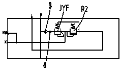
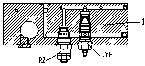
[0024] Such as Figure 1 to Figure 6 As shown, the icon numbers are as follows: oil inlet unit 1, unit basic unit 2, transition net body 3, first damping body 4, valve stem 5, return spring 6, throttle groove 7, working oil passage A, working oil passage B, unit proportional reversing valve DV, pilot pressure reducing valve JYF, drain passage L, sensitive circuit LS, pressure oil passage P, unit secondary relief valve PR, first safety valve R1, second safety valve R2, The third safety valve R3, the unit proportional compensation valve SC, the return oil passage T, the pilot oil passage X, the protection safety valve XLF, and the unit electromagnetic proportional pressure reducing valve Y.

[0025] In the embodiment of the present invention, the integrated electro-hydraulic proportional hydraulic valve group includes the oil inlet unit 1 and t...


PUM


Abstract

The invention discloses an integrated electro-hydraulic proportional hydraulic valve bank, which includes an oil inlet pair and a unit basic pair that are matched in an adhering way, wherein the oil inlet pair is internally provided with a pilot-operated reducing valve and a first safety valve; the inlets of the pilot-operated reducing valve and the first safety valve are connected with a pressure oil passage; the outlet of the pilot-operated reducing valve is connected with a pilot oil passage, and the outlet of the first safety valve is connected with an oil return passage; the unit basic pair is internally provided with unit proportional reversing valves, and unit electromagnetic proportional reducing valves are mounted at the two drive ends of each unit proportional reversing valve; the pressure opening of each unit proportional reversing valve is connected with the pilot oil passage; the proportional speed regulation superimposition and multiple actuating mechanisms are adopted, and the proportional flowrate distribution during the linkage operation is free from the influences of the external load variation and the maximum pump output; the pressure stabilizing oil source arranged on the oil inlet pair provides a pilot oil source for the system; and by adopting the electromagnetic proportional reducing valve on the two sides of the basic pair to control the pushing of the valve rod, the electric signals are converted into hydraulic force, and the repeatability precision is high.

Description

technical field [0001] The invention relates to the technical field of hydraulic systems, in particular to an integrated electro-hydraulic proportional hydraulic valve group, which is suitable for variable pump systems of hydraulic vehicle cranes in engineering machinery. Background technique [0002] With the continuous development of my country's truck crane industry and the continuous advancement of hydraulic system technology, in order to meet various working conditions, people have higher and higher requirements for the accuracy and stability of crane operations. [0003] Modern hydraulic engineering machinery, while pursuing the high efficiency and energy saving of proportional speed regulation and proportional flow distribution, in order to meet various installation and other operation requirements, the requirements for operating valves are also getting higher and higher, and its performance directly affects the performance of the whole machine. Performance directly a...

Claims


Application Information

Patent Timeline
Patent Type & Authority Patents(China)
IPC IPC(8): F15B13/02
Inventor 卢宇
Owner 卢宇
Why Eureka
Try Eureka